Solar steam thermoelectric system

A solar steam and thermoelectric system technology, applied in solar thermal power generation, use of solar energy to generate mechanical power, machines/engines, etc., can solve the problems of high power generation cost, low photovoltaic power conversion efficiency, pollution, etc., and achieve high light energy conversion efficiency. , Improve the efficiency of light energy conversion, the effect of high conversion efficiency

Inactive Publication Date: 2016-12-07
杨小份
View PDF8 Cites 1 Cited by
  • Summary
  • Abstract
  • Description
  • Claims
  • Application Information

AI Technical Summary

Problems solved by technology

[0003] The current solar power generation system has its own advantages and disadvantages, for example: the conversion efficiency of photovoltaic power generation is too low, and the pollution in the manufacturing process is serious, and the unit power generation cost is relatively high; the current solar Stirling technology is not very mature, and the Stirling engine needs to focus on The sunlight reaches a very high temperature (700°) to operate, and the photoelectric conversion efficiency is not very high; the conversion efficiency of the solar thermal molten salt heat storage power generation system is also very low, etc.
[0004] Now the solar Stirling power generation system has been paid more and more attention by people, and it has been developing faster and faster in recent years. The distribution of resource reserves matches; the second is the highest thermal efficiency; the third is its compact structure and easy installation, but the current peak power generation efficiency is 30%, and the heat loss of the original Stirling engine is 2 to 3 times that of the internal combustion engine. Therefore, since 1816 It has not been vigorously promoted since its invention

Method used


Image

  • Solar steam thermoelectric system
  • Solar steam thermoelectric system
  • Solar steam thermoelectric system

Examples


Embodiment 1

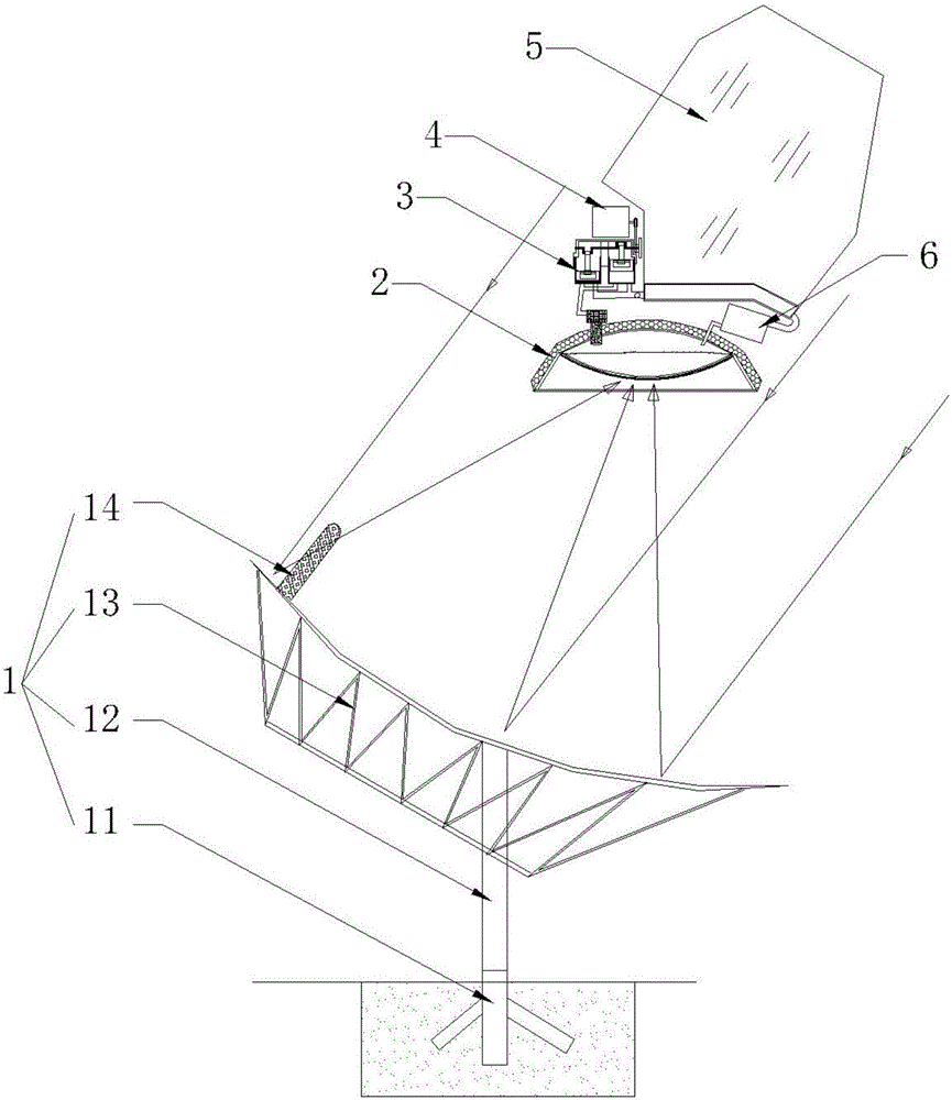
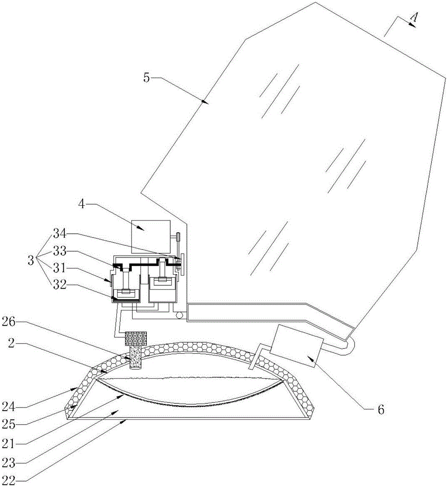
[0063] figure 1 A schematic structural view of the first embodiment of the solar steam thermoelectric system provided by the present invention; figure 2 for figure 1 A partial enlarged view of the solar steam thermoelectric system shown; image 3 for figure 2 The sectional view of the steam cooling device of the shown solar steam thermoelectric system in the direction A; Figure 4 for figure 2 Schematic diagram of the structure of the steam cooling device of the solar steam thermal power system shown.

[0064] Such as figure 1 with figure 2 As shown, the present embodiment provides a solar steam thermoelectric system, comprising:

[0065] A solar energy collection component 1 for collecting solar energy and increasing its energy density;

[0066] A high-pressure hot water boiler 2 for processing liquid water into high-pressure water vapor, and the high-pressure hot water boiler 2 is located at the energy output end of the solar energy collection component 1;

[00...

Embodiment 2

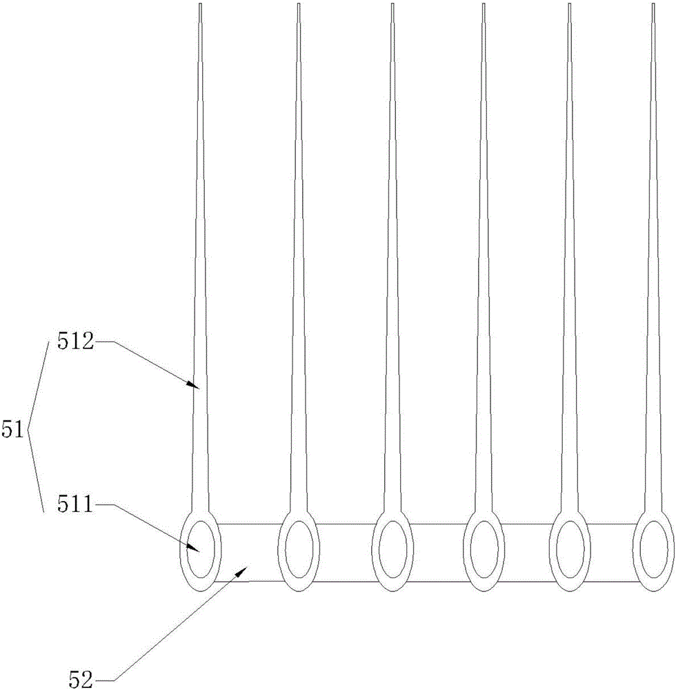
[0087] Figure 5 A partial structural schematic diagram of the second embodiment of the solar steam thermoelectric system provided by the present invention; Image 6 for Figure 5 The sectional view of the steam cooling device of the solar steam thermal power system shown in the B direction; Figure 7 for Figure 5 Schematic diagram of the structure of the steam cooling device of the solar steam thermal power system shown.

[0088] Such as Figure 5-7 As shown, the difference between the solar steam thermal power system provided in this embodiment and the first embodiment lies in the steam cooling device 5 . In this implementation, the steam heat dissipation device 5 includes a cylinder body, a heat dissipation coil 55 and a heat dissipation fan 56; , the other end is connected with the high-temperature water pressure return device 6, and the cooling fin 51 can also be connected on the cooling coil 55;

[0089]After the high-pressure water vapor has done work, it is inpu...

Embodiment 3

[0093] Figure 8 A schematic structural view of the third embodiment of the solar steam thermoelectric system provided by the present invention; Figure 9 for Figure 8 Schematic diagram of the structure of the steam cooling device of the solar steam thermal power system shown.

[0094] Such as Figure 8 with 9 As shown, the difference between the solar steam thermal power system provided in this embodiment and the first and second embodiments lies in the steam cooling device.

[0095] In this implementation, the steam cooling device includes a heat exchange coil 57, a steam pipe 58, a water pump 59 and a flow rate controller; The outer tubes of the exchange coil 57 are wrapped by an insulating layer to reduce heat loss, and the entire heat exchange coil 57 is tightly wrapped with an insulating material; One end is connected with the high-temperature water pressure return device 6; the outer wall of the outer tube of the heat exchange coil 57 is provided with a water inle...


PUM


Abstract

The invention provides a solar steam thermoelectric system and belongs to the field of power generation equipment. The solar steam thermoelectric system comprises a solar energy collecting assembly, a high-pressure hot water boiler, a steam converting power device, a generator, a steam radiator and a high-temperature water pressing-back device. The high-pressure hot water boiler is located at the energy output end of the solar energy collecting assembly. The steam converting power device is provided with a high-pressure water steam input end, a power output end and a lower-pressure water steam output end. The high-pressure water steam input end is connected with the high-pressure hot water boiler. The generator is connected with the power output end. The steam radiator is connected with the lower-pressure water steam output end. High-pressure liquid water flows back into the high-pressure hot water boiler through the high-temperature water pressing-back device. According to the solar steam thermoelectric system provided by the invention, after high-pressure water steam does work, the steam radiator lowers the temperature of low-pressure steam to the critical point, low-temperature steam condenses into high-temperature hot water, high-temperature hot water flows back into the high-pressure hot water boiler, the internal energy of water steam can be fully used, and the efficiency of light energy conversion is further improved.

Description

technical field [0001] The invention relates to the field of power generation equipment, in particular to a solar steam thermoelectric system. Background technique [0002] With the development of the economy and the progress of society, clean energy has become an inevitable and social consensus. Now there are all kinds of power devices relying on solar power generation, such as solar panel power generation systems, thermal solar thermal molten salt heat storage power generation systems, solar Stirling power generation systems, tower-type large-scale solar power generation systems, etc. At present, all kinds of solar energy systems are developing towards the characteristics of high power generation efficiency, low cost, safety and high efficiency, and long service life. [0003] The current solar power generation system has its own advantages and disadvantages, for example: the conversion efficiency of photovoltaic power generation is too low, and the pollution in the manuf...

Claims


Application Information

Patent Timeline
Patent Type & Authority Applications(China)
IPC IPC(8): F03G6/06
CPCF03G6/06Y02E10/46
Inventor 杨小份
Owner 杨小份
Why Eureka
Try Eureka