
Drying oven

A technology of drying furnace and drying chamber, which is applied in the directions of drying, drying machine, drying gas arrangement, etc., and can solve the problem of high energy consumption of drying furnace

Inactive Publication Date: 2016-12-07
GREE ELECTRIC APPLIANCES INC
View PDF5 Cites 1 Cited by
  • Summary
  • Abstract
  • Description
  • Claims
  • Application Information

AI Technical Summary

Problems solved by technology

[0004] In the embodiment of the present invention, a drying furnace is provided to solve the problem of high energy consumption of the drying furnace in the prior art

Method used


Image

  • Drying oven

Examples


Embodiment Construction

[0015] The present invention will be described in further detail below in conjunction with the accompanying drawings and specific embodiments, but not as a limitation of the present invention.

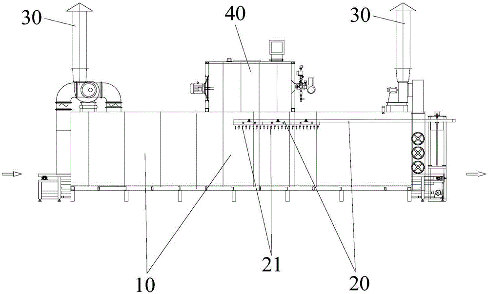
[0016] The drying furnace of the prior art is explained by theoretical analysis and experimental data: the volatile lubricating oil remaining after the air conditioner is mainly left in the inner wall of the fins and copper tubes, the lubricating oil on the fins is easy to volatilize, and the drying The circulating fan in the drying furnace drives the air flow, so the volatilization of the fin drying requires only a small amount of heat energy. The copper tube is a long U-shaped semi-closed structure, and the residual volatile oil therein is difficult to remove.

[0017] According to the above situation, according to an embodiment of the present invention, a drying furnace is provided for drying and degreasing air conditioner components, the air conditioner components include fins and ...


PUM


Abstract

The invention discloses a drying oven used for conducting drying and degreasing on an air conditioner component which comprises fins and copper pipes. The drying oven is provided with a drying chamber used for accommodating the air conditioner component, and further provided with an air blowing device which is movably arranged in the drying chamber. The air blowing device is used for blowing out compressed air with the temperature higher than the drying indoor temperature to orifices of the copper pipes. By means of the drying oven, the problem that a drying oven in the prior art is large in energy consumption is effectively solved.

Description

technical field [0001] The invention relates to the technical field of processing equipment, in particular to a drying furnace. Background technique [0002] Air conditioners (outdoor units and outdoor units) use volatile lubricating oil in the processing of fin punching, copper pipe bending, and pipe expansion, and then in the subsequent processing, the lubricating oil on the fins and copper pipes is Drying and degreasing to ensure welding performance and refrigerant use environment. [0003] In the prior art, the drying furnace heats and dries the two devices (outdoor unit and outdoor unit) as a whole under a certain temperature environment in the furnace, and in order to improve the drying efficiency of the two devices and reduce the final residual oil in the copper pipes of the two devices The amount, the drying temperature in the drying furnace is high, and the long-term continuous operation consumes a lot of energy. Contents of the invention [0004] An embodiment ...

Claims


Application Information

Patent Timeline
IPC IPC(8): F26B9/06F26B21/00
CPCF26B9/06F26B21/004
Inventor 陈学彭楚堂王琳
Owner GREE ELECTRIC APPLIANCES INC
Learn More