Attachment layer reinforced grid ribbed cylindrical shell structure

A ribbed shell and adhesion layer technology, which is applied to projectiles, self-propelled bombs, and offensive equipment, can solve problems such as the decline in ultimate bearing capacity, serious decline, and poor defect resistance of the bare shell structure, achieving improved The effect of bending stiffness

Inactive Publication Date: 2016-12-07
DALIAN UNIV OF TECH
5 Cites 0 Cited by

AI-Extracted Technical Summary

Problems solved by technology

However, the axial pressure critical instability load obtained by theoretical calculation or numerical simulation of the ideal model for this structure is higher than the actual experimental results....

Method used

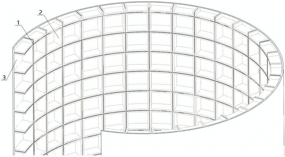
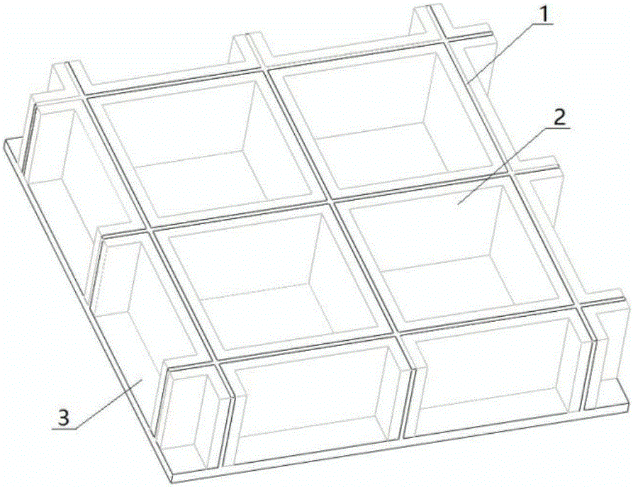
As shown in Figure 1-3, the present invention is a kind of novel adhesion layer reinforced grid ribbed shell structure, increases soft material adhesion layer 2 on the single rib plate 1 surface of traditional grid ribbed structure, thereby improves Comply with the flexural stiffness of the ribbed section. The density of the soft material adhesion layer 2 is smaller than that of the rib 1 material, and the height of the soft material adhesion layer 2 is the same as that of the rib 1 .
At last, with prefabricated side length 78mm, thick 5mm, high 5mmPMI foam square frame, be attached to the rib plate both sides of traditional grid ribbed shell structure by epoxy resin adhesive, can complete adhesion layer reinforcement grid Fabrication of ribbed shell structures. Compared with the traditional grid ribbed shell, the new adhesion layer reinforced grid ribbed shell has the same quality, but the ultimate bearing capacity of axial compression is increased by about 80%.
[0026] Where...

Abstract

The invention discloses an attachment layer reinforced grid ribbed cylindrical shell structure; a soft material attachment layer is added on a rib plate surface of a ribbed structure; and a ribbed form includes but not limited to a rectangular, hexagonal or triangular form. The soft attachment layer is a soft material with lower density compared with a rib plate; and the soft layer is as high as the rib plate. As the bending resistance of the section of the rib plate is improved, the axial load limit bearing capacity of the grid ribbed cylindrical shell structure is effectively increased, or even the structure lightness is realized on this basis; and the grid ribbed form includes but not limited to a rectangular grid, a hexagonal grid and a triangular grid. The grid size in grid ribbing, the width of the rib plate, the height of the rib plate and the width of the soft attachment layer are analytically analyzed according to such engineering indexes as structural size, structural weight and bearing capacity, or are determined by a numerical value optimizing method. A machining process is simple, is convenient for modification of a traditional manufacturing process, and is suitable for large-scale volume production.

Application Domain

Technology Topic

Image

  • Attachment layer reinforced grid ribbed cylindrical shell structure
  • Attachment layer reinforced grid ribbed cylindrical shell structure
  • Attachment layer reinforced grid ribbed cylindrical shell structure

Examples

  • Experimental program(1)

Example Embodiment

[0019] The present invention will be described in detail below in conjunction with the accompanying drawings and embodiments.
[0020] like Figure 1-3 As shown, the present invention is a new type of adhesion layer reinforced grid ribbed shell structure, adding a soft material adhesion layer 2 on the surface of a single rib plate 1 of the traditional grid ribbed structure, thereby improving the bending stiffness of the cross section of the rib plate. The density of the soft material adhesion layer 2 is smaller than that of the rib 1 material, and the height of the soft material adhesion layer 2 is the same as that of the rib 1 .
[0021] Wherein, the grid size, rib width, rib height, and attached soft layer 2 width of the grid ribbing 1 can be determined by analytical analysis or numerical optimization methods according to engineering indicators such as structural size, structural weight, and bearing capacity.
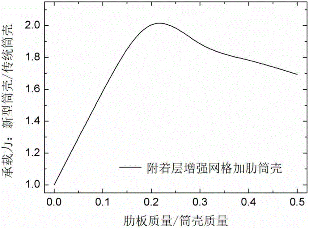
[0022] Wherein, the soft material of the adhesion layer refers to lightweight porous structures such as metal foam (aluminum foam), plastic foam (PMI) and wood, which can be reasonably selected according to engineering material manuals combined with theoretical analysis.
[0023] Wherein, the grid-ribbed cylindrical shell structure reinforced by the adhesion layer includes but not limited to: rectangular grid, hexagonal grid and triangular grid, such as Figure 4-5 shown.
[0024] Wherein, the adhesion layer reinforced grid ribbed cylindrical shell structure is not limited to only adding a soft material adhesion layer on the surface of the ribs, and can add a soft material adhesion layer on the inner surface of the skin and the ribs at the same time according to engineering requirements.
[0025] Wherein, the adhesion layer reinforced grid ribbed cylindrical shell structure is not limited to only adding a soft material adhesion layer on the surface of the ribs, and can add a soft material adhesion layer on the inner surface of the skin and the ribs at the same time according to engineering requirements.
[0026] Wherein, the skin 3 and the ribs 1 in the adhesive layer-reinforced mesh-ribbed shell structure can be integrally formed by chemical milling or mechanical milling. The soft material adhesion layer 2 in the grid-ribbed shell structure reinforced by the adhesion layer can be directly manufactured and shaped according to the grid-rib form. By controlling the width of the rib plate 1 and the width of the attachment layer 2, the bending stiffness of the composite rib plate section can be improved, and then under the condition of equal mass, the grid ribbed shell structure with greater axial compressive ultimate bearing capacity can be obtained, or under the same load Under the requirements, the grid ribbed shell structure can be reduced in weight. The width of the core ribs in the grid-ribbed cylindrical shell structure reinforced by the adhesion layer should be smaller than that in the traditional design, so as to offset the additional mass of the soft material adhesion layer introduced.
[0027] Taking an actual structure as an example, the implementation method can be divided into 3 steps:
[0028] Firstly, a square traditional grid ribbed aluminum plate (2A14T6 aluminum alloy) with a grid size of 80 mm, a rib height of 40 mm, a rib width of 2 mm, and a skin thickness of 5 mm was processed by chemical milling or mechanical milling.
[0029] Then, the processed grid-ribbed plate structure is rolled and formed, and the joints are welded by friction stir welding to obtain a traditional grid-ribbed shell structure with a height of 1000 mm and a diameter of 990 mm.
[0030] Finally, the prefabricated PMI foam square frame with a side length of 78mm, a thickness of 5mm, and a height of 5mm is attached to both sides of the rib plate of the traditional grid-ribbed shell structure through epoxy resin adhesive, and the attachment layer reinforced grid-ribbed shell can be completed. Fabrication of shell structures. Compared with the traditional grid ribbed shell, the new adhesion layer reinforced grid ribbed shell has the same quality, but the ultimate bearing capacity of axial compression is increased by about 80%.

PUM

no PUM

Description & Claims & Application Information

We can also present the details of the Description, Claims and Application information to help users get a comprehensive understanding of the technical details of the patent, such as background art, summary of invention, brief description of drawings, description of embodiments, and other original content. On the other hand, users can also determine the specific scope of protection of the technology through the list of claims; as well as understand the changes in the life cycle of the technology with the presentation of the patent timeline. Login to view more.

Similar technology patents

Multi-cell metal porous structure

Owner:SHENZHEN CANSINGA TECH CO LTD

Classification and recommendation of technical efficacy words

People also interested in

Why Eureka
Try Eureka