Thermocouple transducer time constant testing device and method

A thermocouple sensor and time constant technology, applied in measurement devices, thermometer testing/calibration, instruments, etc., can solve the problems of low excitation temperature, high cost, unsatisfactory excitation signal, etc., and achieve accurate time constant and clear high and low temperature interface. , The effect of not easy to damage

Inactive Publication Date: 2016-12-07
ZHONGBEI UNIV
View PDF8 Cites 16 Cited by
  • Summary
  • Abstract
  • Description
  • Claims
  • Application Information

AI Technical Summary

Problems solved by technology

[0003] In order to solve the problems of low excitation temperature, unsatisfactory excitation signal, high cost, destructiveness and inability to accurately obtain the time constant in the combustion environment in the existing thermocouple sensor time constant test method, the present invention provides a thermocouple sensor time constant Constant testing device and method

Method used


Image

  • Thermocouple transducer time constant testing device and method
  • Thermocouple transducer time constant testing device and method

Examples


Embodiment Construction

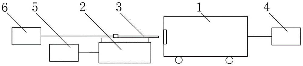
[0017] A thermocouple sensor time constant testing device, comprising a verification furnace 1, a linear servo guide rail 2, a thermocouple sensor 3, a temperature controller 4, a servo controller 5, and a data acquisition and processing device 6; wherein, the thermocouple sensor 3 is fixed on a linear On the slider of the servo guide rail 2, and the temperature measuring end of the thermocouple sensor 3 is kept facing the entrance of the verification furnace 1; the signal transmission end of the temperature controller 4 is bidirectionally connected with the signal transmission end of the verification furnace 1; the servo controller 5 The signal transmission end of the signal transmission end is bidirectionally connected with the signal transmission end of the linear servo guide rail 2; the signal input end of the data acquisition and processing device 6 is connected with the signal output end of the thermocouple sensor 3.

[0018] The linear servo guide rail 2 is a linear AC s...


PUM

PropertyMeasurementUnit
lengthaaaaaaaaaa
lengthaaaaaaaaaa

Abstract

The invention relates to the technology of thermocouple transducer time constant testing, in particular to a thermocouple transducer time constant testing device and method. The thermocouple transducer time constant testing device and method solve the problems that an existing thermocouple transducer time constant testing method is low in excitation temperature, unsatisfactory in excitation signal, high in cost, destructive and incapable of accurately obtaining a time constant in a combustion environment. The thermocouple transducer time constant testing device comprises a verification furnace, a linear servo guide rail, a thermocouple transducer, a temperature controller, a servo controller and a data collecting and processing device. The thermocouple transducer is fixed to a sliding block of the linear servo guide rail, and the temperature measuring end of the thermocouple transducer is maintained to exactly face an inlet of the verification furnace. The signal transmission end of the temperature controller is in bidirectional connection with the signal transmission end of the verification furnace. The thermocouple transducer time constant testing device and method are suitable for testing the time constants of various thermocouple transducers and especially suitable for testing the time constants of various thermocouple transducers in the combustion temperature field environment.

Description

technical field [0001] The invention relates to a time constant testing technology of a thermocouple sensor, in particular to a thermocouple sensor time constant testing device and method. Background technique [0002] In the field of dynamic temperature testing, the dynamic performance of thermocouple sensors is the key to the testing accuracy. Due to the thermal inertia of the temperature sensing part of the thermocouple sensor, there is a dynamic error in the dynamic temperature test. Therefore, it is very important to dynamically calibrate the thermocouple sensor, and the time constant of the thermocouple sensor is the main technical index reflecting its dynamic characteristics, so it is necessary to test the time constant of the thermocouple sensor. Under the existing technical conditions, the time constant test methods of thermocouple sensors mainly include constant temperature water / oil tank method, shock tube method, hot wind tunnel method and laser method. The con...

Claims


Application Information

Patent Timeline
Patent Type & Authority Applications(China)
IPC IPC(8): G01K15/00
CPCG01K15/007
Inventor 张志杰李岩峰王巍赵晨阳王振
Owner ZHONGBEI UNIV
Why Eureka
Try Eureka