Integrating method of three-dimensional spatial distribution vortex arrays

A technology of spatial distribution and integration method, applied in the field of diffractive optics, which can solve the problems of uneven diffraction efficiency, high system complexity, and inability to generate different topological charges.

Active Publication Date: 2016-12-07
BEIJING INSTITUTE OF TECHNOLOGYGY
View PDF5 Cites 28 Cited by
  • Summary
  • Abstract
  • Description
  • Claims
  • Application Information

AI Technical Summary

Problems solved by technology

[0007] The purpose of the present invention is to solve the problems of high system complexity, uneven diffraction efficiency and inability to generate three-dimensional arrays with different topological charge numbers in the prior art, and to provide an in

Method used


Image

  • Integrating method of three-dimensional spatial distribution vortex arrays
  • Integrating method of three-dimensional spatial distribution vortex arrays
  • Integrating method of three-dimensional spatial distribution vortex arrays

Examples


Embodiment Construction

[0061] The present invention will be described in detail below in conjunction with the accompanying drawings and embodiments. The specific embodiments described here are only used to explain the present invention, not to limit the present invention.

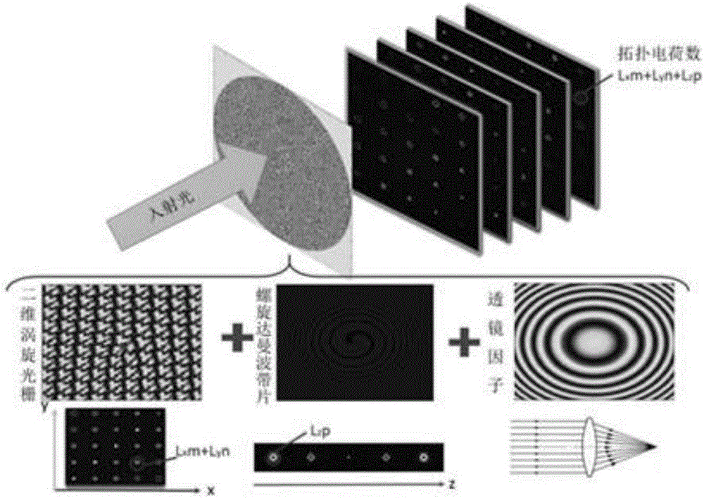
[0062] The integration method of a spatially distributed three-dimensional vortex array according to the present invention, the specific process is:

[0063] The design method to generate a 3D vortex array consists of three parts:

[0064] (1) Design of two-dimensional uniform intensity vortex grating

[0065] Two-dimensional uniform intensity vortex gratings can be realized by spatial superposition and intensity optimization of one-dimensional vortex gratings. Among them, the one-dimensional vortex grating transmittance function can be expressed as:

[0066]

[0067] That is, vortex beams with nl topological charges are generated on different orders respectively. Take the phase value of the grating, multiply it with the r...


PUM


Abstract

The invention relates to an integrating method of three-dimensional spatial distribution vortex arrays, and belongs to the field of diffraction optics. A pure-phase code of a two-dimensional uniform-strength vortex optical grating and a pure-phase code of a spiral Dammam wave zone plate are obtained through analytic operation and an optimization algorithm respectively, phase information of the pure-phase codes is overlaid, a lens factor is introduced, discretized phase values are loaded to a spatial light modulator according to the pixel number and the pixel size of the spatial light modulator, and then the corresponding three-dimensional vortex arrays can be obtained. According to the method, the equal-strength and regular-distribution three-dimensional vortex arrays can be obtained, and each vortex beam in the arrays has the specific topological charge number.

Description

technical field [0001] The invention relates to an integration method of a spatially distributed three-dimensional vortex array, belonging to the field of diffractive optics. Background technique [0002] A vortex beam has a continuous helical wavefront whose phase can be expressed as where l is called the topological charge number of this helical phase, is the azimuth angle. The central point of the vortex beam has phase uncertainty, called phase singularity, and the amplitude at this point is zero, thus forming a special form of light field distribution with a dark spot in the center and bright spots around it. The energy flux density vector of a vortex beam has a tangential component, and thus has an orbital angular momentum. For a vortex beam with topological charge l, the angular momentum carried by each photon is This angular momentum can be transferred to illuminated objects, such as particles, cells or atoms. The characteristics of vortex beams make them have...

Claims


Application Information

Patent Timeline
IPC IPC(8): G02B5/18G02B27/00G02B27/42G02B27/44G02B27/46
CPCG02B5/1876G02B27/0012G02B27/4266G02B27/44G02B27/46
Inventor 黄玲玲宋旭王涌天
Owner BEIJING INSTITUTE OF TECHNOLOGYGY
Why Eureka
Try Eureka