A Two-Dimensional Reconfigurable Orthogonal Coupler
An orthogonal coupler and coupler technology, applied in the field of microwave radio frequency, can solve the problems of general flexibility and adaptability, the inability to adjust the center frequency and power division ratio at the same time, and achieve signal quadrature output easy processing, center frequency and Reconfigurable Effects of Power Split Ratio
- Summary
- Abstract
- Description
- Claims
- Application Information
AI Technical Summary
Problems solved by technology
Method used
Image
Examples
Embodiment 1
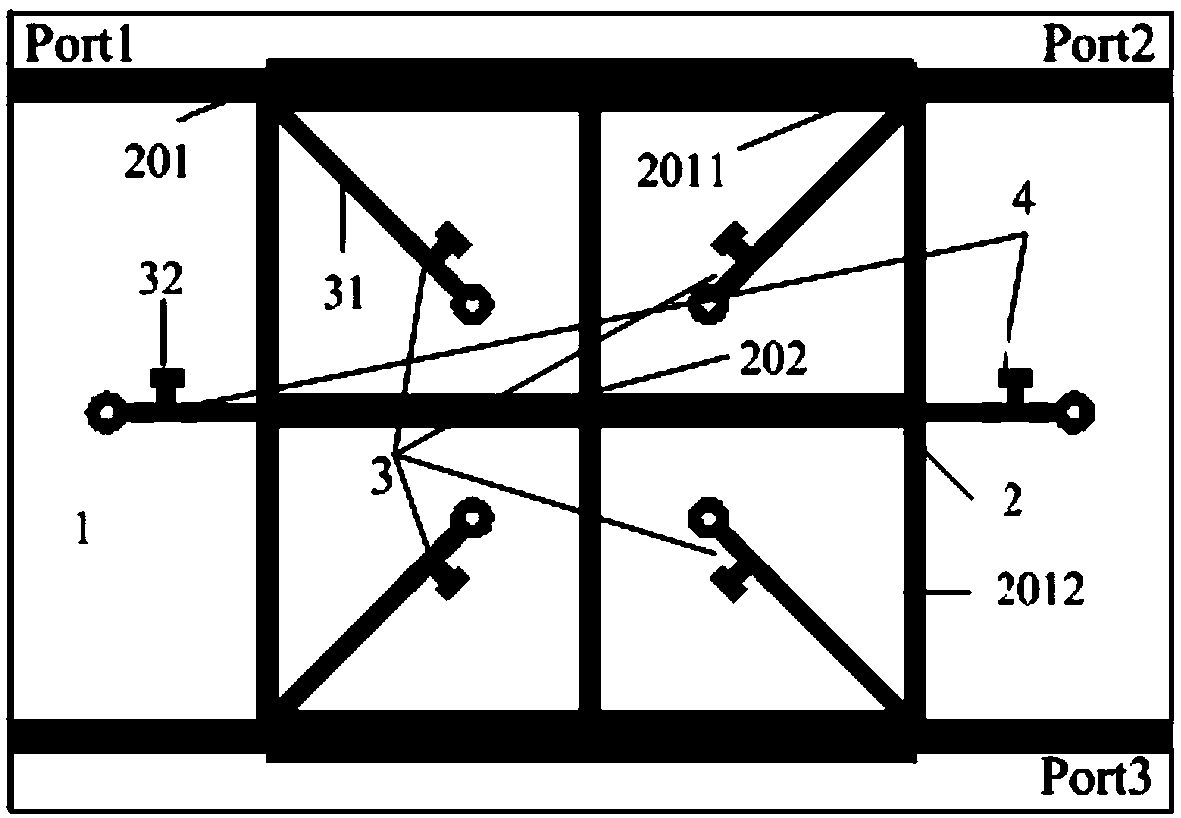
[0039] Embodiment 1 of the present invention discloses a two-dimensional reconfigurable quadrature coupler, the schematic diagram of which is shown in figure 1 As shown, the two-dimensional reconfigurable orthogonal coupler 100 includes: a dielectric board 1;
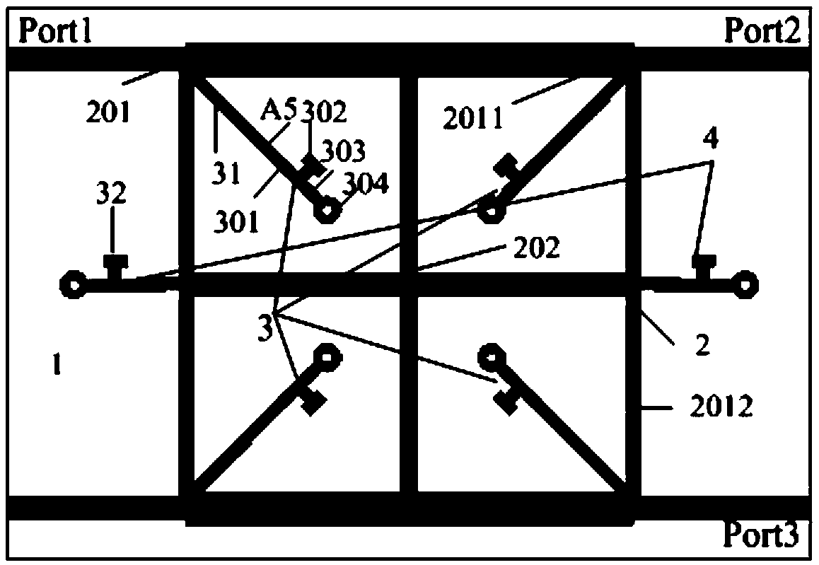
[0040] An improved branch coupler 2, a frequency modulation bias unit 3 and a power modulation ratio bias unit 4 arranged on the dielectric board 1;
[0041] Wherein, the improved branch line coupler 2 is a square structure composed of the basic branch line coupler 201 and the cross-shaped microstrip line 202, and the frequency modulation bias unit 3 includes four frequency modulation bias circuits 31, and the power modulation ratio bias The unit 4 includes two power adjustment ratio bias circuits 32;
[0042] The input ends of each frequency modulation bias circuit 31 are respectively connected with the four intersection points of the series arm 2011 and the parallel arm 2012 surrounded by a rectangle in the basic bra...
Embodiment 2
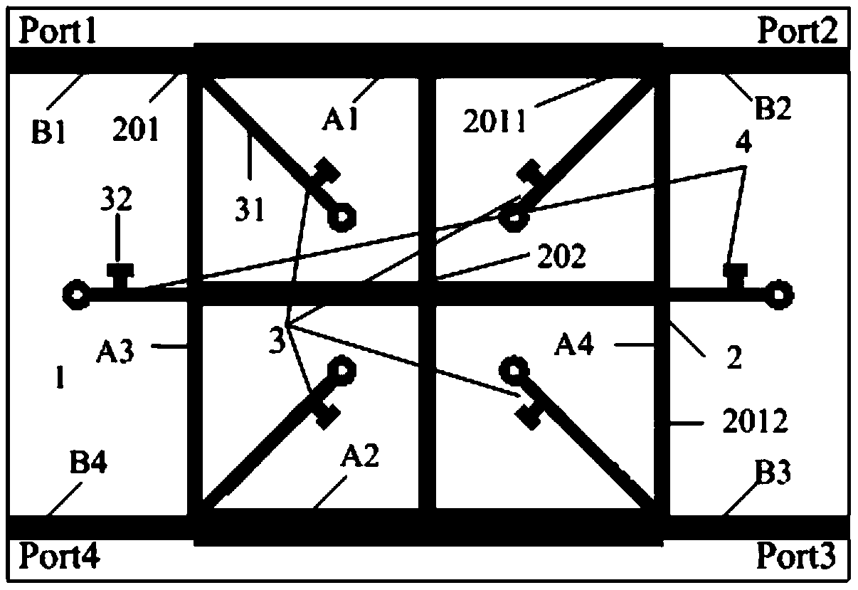
[0047] Based on the two-dimensional reconfigurable quadrature coupler disclosed in the first embodiment of the present invention and the attached figure 1 , Embodiment 1 of the present invention also discloses a two-dimensional reconfigurable quadrature coupler, the schematic diagram of which is shown in figure 2 As shown, the basic branch line coupler 201 specifically includes: four port impedance matching lines B1, B2, B3, B4, a series arm 2011 and a parallel arm 2012;
[0048] Wherein, the series arm 2011 includes a first microstrip line A1 and a second microstrip line A2 that are parallel to each other and have a consistent structure, and the parallel arm 2012 includes a third microstrip line A3 and a fourth microstrip line A4 that are parallel to each other and have a consistent structure; One end of the four port impedance matching lines B1, B2, B3, B4 is respectively tapped at both ends of the first microstrip line A1 and the second microstrip line A2, and the other en...
example 1
[0061] In order to obtain the application scenario of a high-frequency signal with a center frequency of 0.7GHz and a power division ratio of 0dB, the S-parameter simulation and test results are shown in the figure Figure 5 As shown, the phase simulation and test results are shown in Image 6 shown;
[0062] When the first preset bias voltage is 2.3V and the second preset bias voltage is 7.3V, the input port Port1 of the improved branch line coupler 2 is connected to the first microwave signal, and each frequency modulation in the frequency modulation bias unit 3 The bias circuit 31 adjusts the equivalent electrical lengths of the series arm and the parallel arm of the improved branch line coupler 2 based on the first preset bias voltage of 2.3V and the first microwave signal; at the same time, each of the frequency modulation bias unit 3 The power ratio bias circuit 32 adjusts the equivalent impedance of the parallel arm of the improved branch line coupler 2 based on the se...
PUM
 Abstract
Description
Claims
Application Information
 - R&D
- Intellectual Property
- Life Sciences
- Materials
- Tech Scout
- Unparalleled Data Quality
- Higher Quality Content
- 60% Fewer Hallucinations
Browse by: Latest US Patents, China's latest patents, Technical Efficacy Thesaurus, Application Domain, Technology Topic, Popular Technical Reports.
© 2025 PatSnap. All rights reserved.Legal|Privacy policy|Modern Slavery Act Transparency Statement|Sitemap|About US| Contact US: help@patsnap.com


