
A PDMS microfluidic chip structure and preparation method thereof

A microfluidic chip and microfluidic technology, applied in chemical instruments and methods, laboratory utensils, laboratory containers, etc., can solve the problems of increasing the processing cost of microfluidic chips, and achieve uniform and controllable size. Simple preparation method and small flow resistance

Active Publication Date: 2018-10-30
HANGZHOU DIANZI UNIV
View PDF8 Cites 0 Cited by
  • Summary
  • Abstract
  • Description
  • Claims
  • Application Information

AI Technical Summary

Problems solved by technology

Moreover, the smaller the size of the rectangular section, the higher the processing cost of the microfluidic chip.

Method used


Image

  • A PDMS microfluidic chip structure and preparation method thereof
  • A PDMS microfluidic chip structure and preparation method thereof
  • A PDMS microfluidic chip structure and preparation method thereof

Examples


Embodiment 1

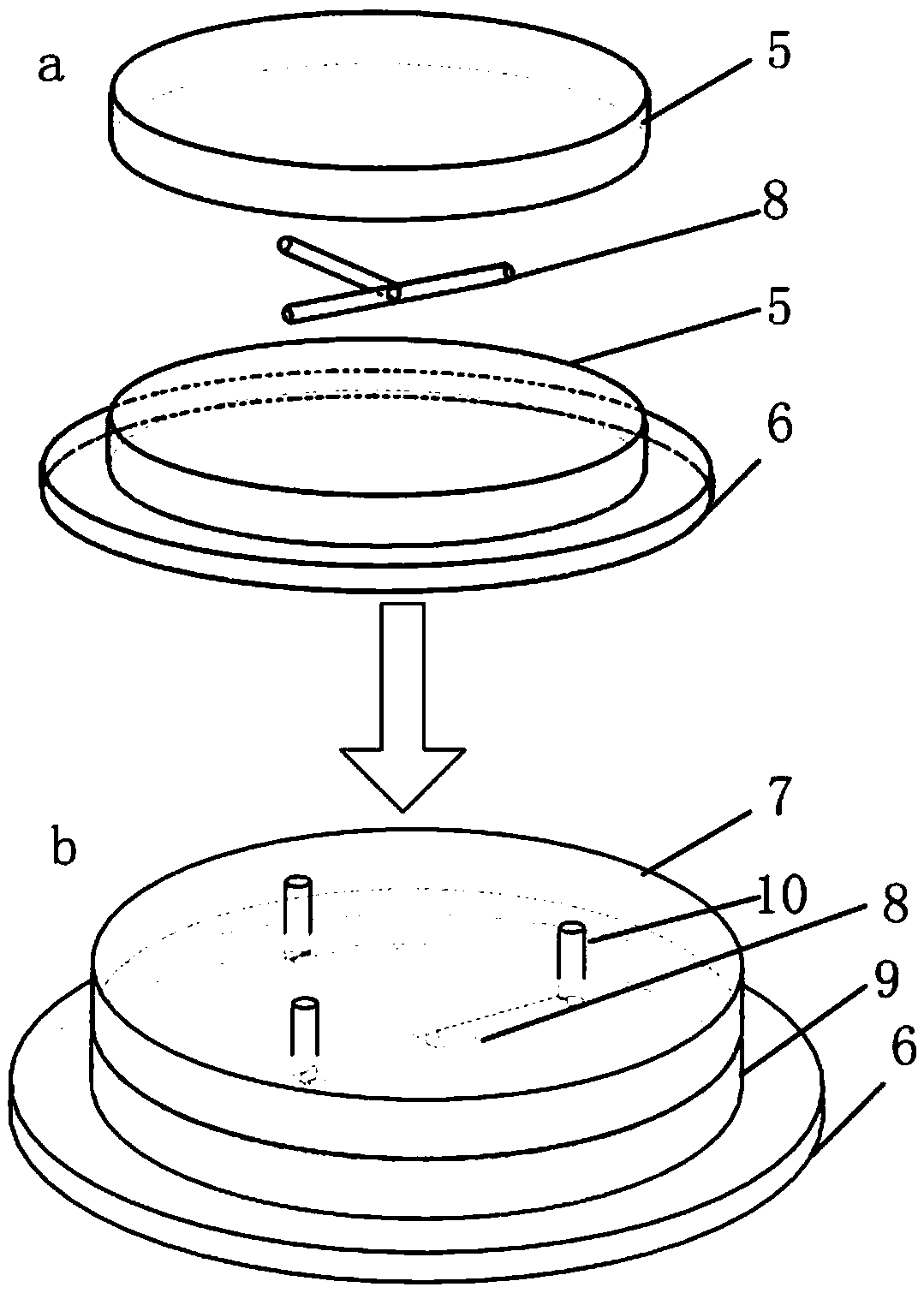
[0031] like image 3 As shown, the PDMS microfluidic chip of this embodiment includes an upper PDMS microfluidic chip 7 and a lower PDMS microfluidic chip 9, and a T-shaped glass is fixed between the upper PDMS microfluidic chip 7 and the lower PDMS microfluidic chip 9. The capillary microchannel 8 and the cross section of the glass capillary microchannel 8 are circular. Compared with the existing rectangular section, it has the advantages of small flow resistance, uniform and controllable size, simple forming process and good surface quality.

[0032] The preparation method of the PDMS microfluidic chip of the present embodiment comprises the following steps:

[0033] 1) Formation of circular cross-section glass microchannels:

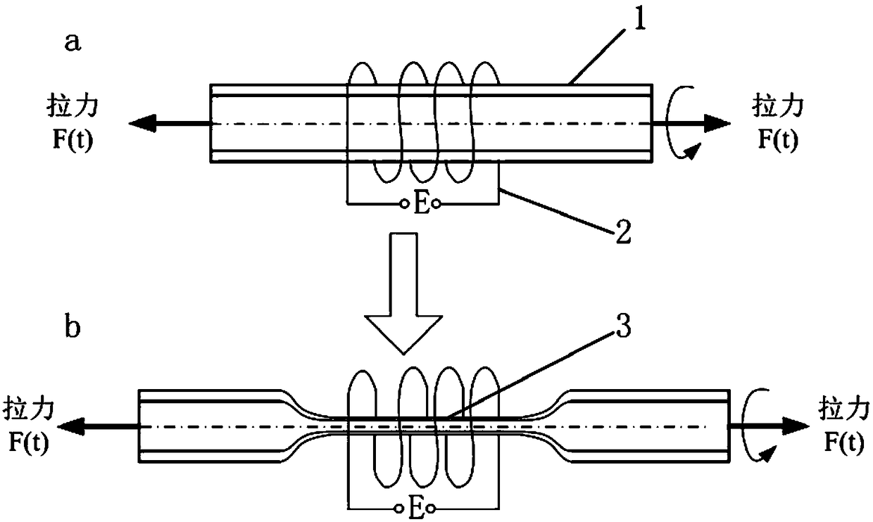
[0034] like figure 1 As shown, the two ends of the glass capillary 1 with an outer diameter of 1.0 mm, an inner diameter of 0.6 mm, and a length of 100 mm are clamped vertically on two fixtures. slide. The glass capillary 1 is made of borosilicate...

Embodiment 2

[0047] The difference between this embodiment and Embodiment 1 is that a borosilicate glass capillary tube with an outer diameter of 5.0 mm, an inner diameter of 2.0 mm, and a length of 100 mm is drawn to form a glass microchannel, and a glass with a circular cross-section of 20 cm is obtained. Micro-channel, three glass micro-channels with a circular cross-section with a length of 20cm are placed on the surface of the lower PDMS prepolymer in a semi-cured state to form a Y-shaped glass capillary micro-channel according to the Y-shaped shape; the microfluidic chip The cross-section of the mold is replaced by a circle to a rectangle, and other structures and preparation steps refer to Example 1.

Embodiment 3

[0049] The difference between this embodiment and Embodiment 1 is that a quartz glass capillary with an outer diameter of 7.5 mm, an inner diameter of 5.0 mm, and a length of 200 mm is drawn to form a glass microchannel, and a glass microchannel with a circular cross-section of 30 cm is obtained. , three circular cross-section glass microchannels with a length of 30 cm are placed on the surface of the lower PDMS prepolymer in a semi-cured state according to a Y shape to form a Y-shaped glass capillary microchannel; the transverse direction of the microfluidic chip mold The cross-section is replaced by a triangle, and other structures and preparation steps refer to Example 1.


PUM


Abstract

The invention belongs to the technical field of microfluidic chips and particularly relates to a PDMS (polydimethylsiloxane) microfluidic chip structure. The PDMS microfluidic chip structure comprises a lower PDMS microfluidic chip, a glass capillary microfluidic channel and an upper PDMS microfluidic chip which are arranged from bottom to top sequentially, and the section of the glass capillary microfluidic channel is circular. The invention further discloses a preparation method of the PDMS microfluidic chip structure. The preparation method includes steps: 1) preparing a glass microfluidic channel; 2) pouring to form a lower PDMS prepolymer; 3) heating until the lower PDMS prepolymer is in a semi-solidified state; 4) putting the glass microfluidic channel on the surface of the lower PDMS prepolymer according to a preset shape to form the glass capillary microfluidic channel; 5) pouring to form an upper PDMS prepolymer, and heating until the upper and lower PDMS prepolymers are solidified completely; 6) punching. The preparation method is simple, equipment and processes of male moulds, bonding and the like for PDMS pouring are avoided, and accordingly production cost is low.

Description

technical field [0001] The invention belongs to the technical field of microfluidic chips, and in particular relates to a PDMS microfluidic chip structure and a preparation method thereof. Background technique [0002] Microfluidic chip technology integrates the basic operation units such as sample preparation, reaction, separation, and detection in the biological, chemical, and medical analysis processes into a micron-scale chip to automatically complete the entire analysis process. Due to its great potential in the fields of biology, chemistry, and medicine, it has developed into a new research field interdisciplinary in biology, chemistry, medicine, fluid, electronics, materials, and machinery. Microfluidic chip is the carrier of microfluidic technology, and its material, structure, processing method, microchannel size and surface properties and other factors directly affect the application of microfluidic technology and the effect of microanalysis. Commonly used materia...

Claims


Application Information

Patent Timeline
Patent Type & Authority Patents(China)
IPC IPC(8): B01L3/00
CPCB01L3/5027B01L3/502707B01L2200/10B01L2300/0838
Inventor 王洪成赵苗苗吴立群
Owner HANGZHOU DIANZI UNIV
Learn More