Positioning and clamping device for butt welding of mixer head group and its operation method

A technology for positioning, clamping and operating methods, applied in auxiliary devices, welding equipment, auxiliary welding equipment, etc., can solve the problems of uniformity, low position accuracy, low degree of automation, low processing efficiency, etc., and achieve low labor intensity for workers. , good versatility, high processing efficiency

Active Publication Date: 2018-07-06
ANHUI XINGMA SPECIAL PURPOSE VEHICLE
View PDF7 Cites 2 Cited by
  • Summary
  • Abstract
  • Description
  • Claims
  • Application Information

AI Technical Summary

Problems solved by technology

[0004] This kind of combination welding processing method has limitations, and its disadvantages are: 1. In the early stage of head production, bolts and briquetting blocks are used to compress the flange, and it is completely manual clamping and unloading by workers, and different types of heads are adjusted. It is time-consuming and labor-intensive to replace the corresponding die when flanged; 2. When welding, workers have to enter the die and squat on the head to weld, which will cause some stress on the workpiece, and it is easy to be welded in summer The heat burns, welding is very inconvenient and unsafe; 3. Even with the same type of head, the parts have certain processing tolerances, and this kind of die cannot be adjusted well; the head positioning mold is used for measurement and positioning , The degree of automation of the assembly is low, the uniformity and position accuracy of the produced products are not high, the standardization is poor, and the processing efficiency is low; 4. The relative positional relationship between the head plate and the flange depends entirely on the manufactured Positioning mold control, so poor adjustability

Method used


Image

  • Positioning and clamping device for butt welding of mixer head group and its operation method
  • Positioning and clamping device for butt welding of mixer head group and its operation method
  • Positioning and clamping device for butt welding of mixer head group and its operation method

Examples


Embodiment 1

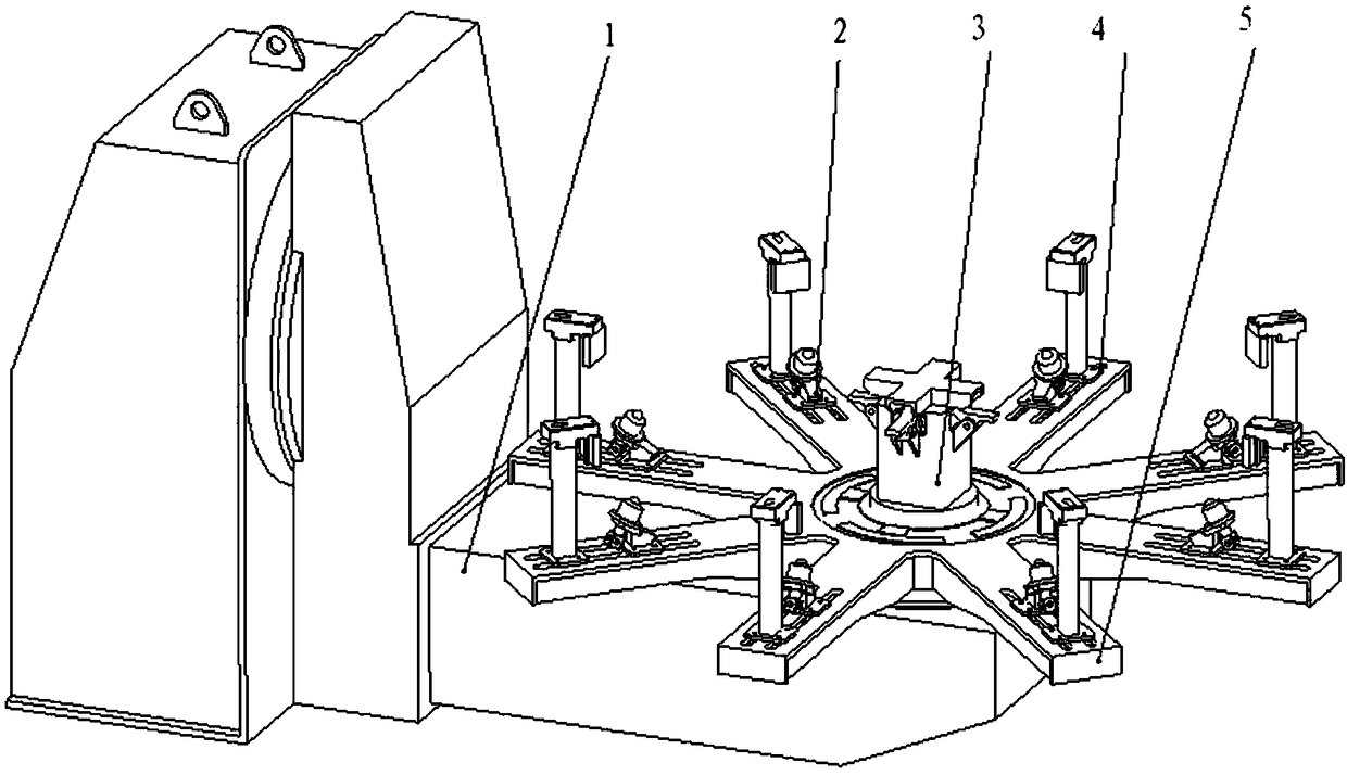
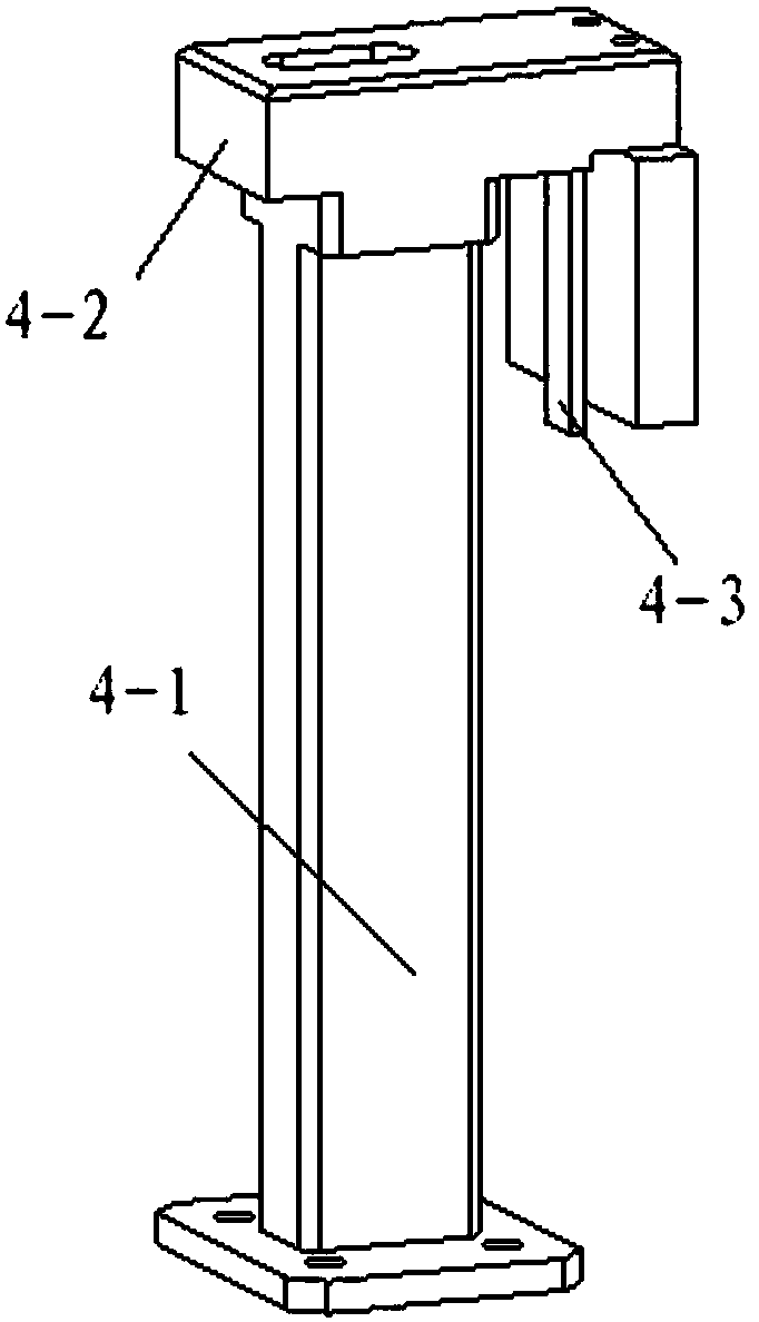
[0030] From figure 2 It can be seen that the positioning and clamping device for butt welding of the head group of the mixer truck in the present invention is characterized in that it includes a ball support 2, a pneumatic compression device 3, a briquetting block 4, and an upper platform 5; a ball support 2 and a pneumatic compression device Both the device 3 and the pressing block 4 are arranged on the upper platform 5 . Among them, the pneumatic clamping device is specially used to compress the flange so that it does not leave its position during the rotary displacement. At the same time, the automatic pneumatic clamping device completes the flange clamping with one key, which is simple and fast. The structure of the pneumatic clamping device is as follows: Figure 5 as shown,

Embodiment 2

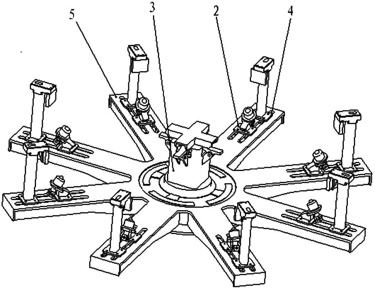
[0032] From figure 1 , figure 2 , Figure 6 It can be seen that the upper platform 5 in the above embodiment is spoke-shaped, with a circular platform in the middle, and there are several cantilevers uniformly distributed along the circumferential direction radiating outward from the outer circle of the circular platform, and each cantilever is provided with a press Block 4, a ball head support 2; the pneumatic pressing device 3 is arranged in the middle of the circular platform at the center of the upper platform 5 .

Embodiment 3

[0034] In the above-described embodiment, each cantilever of the upper platform 5 has two parallel racetrack-shaped through holes as tracks, and the briquetting block 4 and the ball support 2 are connected with the cantilever through the racetrack-shaped through-holes, and the briquetting block 4 is positioned on the ball. The outside of the head support 2. In this way, whether there is a processing tolerance in the parts of the same type of head, or different types of heads with little difference in size, the ball support 2 and the pressing block 4 can be moved and adjusted in the raceway-shaped through hole to realize positioning and clamping. It is tight, thereby improving its versatility, further improving work efficiency, and reducing the workload of workers, saving time and effort.


PUM


Abstract

The invention discloses a locating and clamping device for mixer truck end socket assembling and welding and an operation method thereof. The locating and clamping device for mixer truck end socket assembling and welding comprises ball supports, a pneumatic pressing device, pressing blocks and an upper platform. The ball supports, the pneumatic pressing device and the pressing blocks are arranged on the upper platform. The upper platform is in a spoke shape, a round platform is arranged in the middle, and a plurality of cantilevers distributed uniformly in the circumferential direction are radiated outwards from the outer circle of the round platform. Each cantilever is provided with one pressing block and one ball support. The pneumatic pressing device is arranged in the center of the round platform of the center of the upper platform. For end sockets of the same type with the machining allowance and end sockets of the different types with a little size difference, the locating and clamping device can be used for locating and clamping the end sockets, thus, the universality is improved, the working efficiency is further improved, and workloads of workers are reduced.

Description

technical field [0001] The invention relates to a tooling and an operating method thereof, in particular to a positioning and clamping device for butt welding of a head group of a mixer truck and an operating method thereof. Background technique [0002] The head of the concrete mixer truck is a circular sealing cover located at the front end of the mixer tank (such as Figure 6 shown), generally consists of flanges, inner cover plates, head plates, and ribs (not shown in the figure). Hereinafter, the "concrete mixer truck head" will be referred to as "head" for short. [0003] At present, the butt welding of the head of the concrete mixer truck in the early stage is carried out on the positioning mold of the mixer truck head. According to different types of heads, there are corresponding positioning molds: first place the head positioning mold horizontally, and then place the flange Place it horizontally and centrally on the center platform of the head positioning mold, an...

Claims


Application Information

Patent Timeline
Patent Type & Authority Patents(China)
IPC IPC(8): B23K37/04
CPCB23K37/0443
Inventor 刘尚青黄建成周玉喜郭振伟李大年
Owner ANHUI XINGMA SPECIAL PURPOSE VEHICLE
Why Eureka
Try Eureka