
Multi-stage microfluidisation and deep filtration integrated type improved anaerobic filter

An anaerobic filter and microfluidization technology, applied in anaerobic digestion treatment, chemical instruments and methods, water/sludge/sewage treatment, etc., can solve the problem of insufficient treatment of polluted wastewater, dead zone, Channeling and other problems, to achieve the effect of easy growth of biofilm, sufficient contact and suitable volume space

Inactive Publication Date: 2016-12-14
NANJING UNIV OF TECH
View PDF5 Cites 3 Cited by
  • Summary
  • Abstract
  • Description
  • Claims
  • Application Information

AI Technical Summary

Problems solved by technology

In the biological filter, according to the upward direction of the water flow, there are water inlet buffer, filter filter area, and water outlet buffer. The filter filter area includes the first filter area, the second filter area, the third filter area, and the fourth filter area. , and the height accounts for 20%, 50%, 20% and 10% of the filter area respectively; each filter area is filled with biomass fillers with different raw material ratios, and the biomass fillers are composed of henna plant biomass materials and inert fillers. This patent The sewage is purified by filling the filter area with different ratios of biomass fillers. Since there is no upward air force, channel flow, short flow, and dead zones will appear in the anaerobic filter, so that the polluted wastewater cannot be fully treated. , and the biomass material will eventually be decomposed and needs to be reinvested

Method used


Image

  • Multi-stage microfluidisation and deep filtration integrated type improved anaerobic filter
  • Multi-stage microfluidisation and deep filtration integrated type improved anaerobic filter

Examples


Embodiment 1

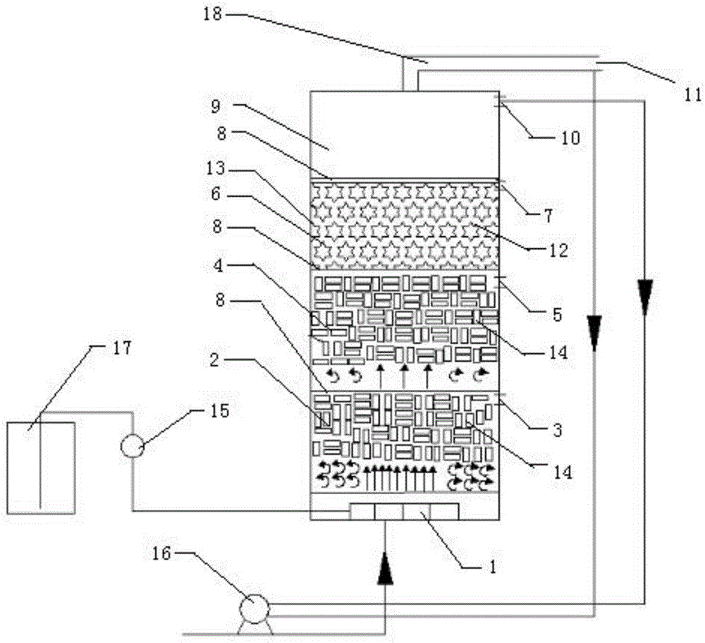
[0025] as attached figure 1 Shown is an improved anaerobic filter 13 with multi-stage microfluidization and depth filtration. The inside of the anaerobic filter 13 is sequentially provided with a water distribution area with a water distributor 1 and a strong Strong microfluidized packing area 2 with sampling port 3 in microfluidized packing area, weak microfluidized packing area 4 with sampling port 5 in weak microfluidized packing area, filter packing area 6 with sampling port 7 in filter packing area , a water outlet area 9 with a water outlet 10 and a biogas collection system (not shown) with an air outlet 11 communicated with the water outlet 9 through a biogas pipeline 18 and the strong microfluidization packing area 2, weak microfluidization A detachable porous partition 8 is arranged between the packing area 4, the filter packing area 6, and the water outlet area 9; the holes of the porous partition 8 are evenly distributed and the pore diameter is less than 1 cm, and ...

Embodiment 2

[0031] as attached figure 1 Shown is an improved anaerobic filter 13 with multi-stage microfluidization and depth filtration. The inside of the anaerobic filter 13 is sequentially provided with a water distribution area with a water distributor 1 and a strong Strong microfluidized packing area 2 with sampling port 3 in microfluidized packing area, weak microfluidized packing area 4 with sampling port 5 in weak microfluidized packing area, filter packing area 6 with sampling port 7 in filter packing area , a water outlet area 9 with a water outlet 10 and a biogas collection system (not shown) with an air outlet 11 communicated with the water outlet 9 through a biogas pipeline 18 and the strong microfluidization packing area 2, weak microfluidization A detachable porous partition 8 is arranged between the packing area 4, the filter packing area 6 and the water outlet area 9; the holes of the porous partition 8 are evenly distributed and the pore diameter is less than 1 cm; the w...

Embodiment 3

[0037] as attached figure 1 Shown is an improved anaerobic filter 13 with multi-stage microfluidization and depth filtration. The inside of the anaerobic filter 13 is sequentially provided with a water distribution area with a water distributor 1 and a strong Strong microfluidized packing area 2 with sampling port 3 in microfluidized packing area, weak microfluidized packing area 4 with sampling port 5 in weak microfluidized packing area, filter packing area 6 with sampling port 7 in filter packing area , a water outlet area 9 with a water outlet 10 and a biogas collection system (not shown) with an air outlet 11 communicated with the water outlet 9 through a biogas pipeline 18 and the strong microfluidization packing area 2, weak microfluidization A detachable porous partition 8 is arranged between the packing area 4, the filter packing area 6 and the water outlet area 9; the holes of the porous partition 8 are evenly distributed and the pore diameter is less than 1 cm; the w...


PUM

PropertyMeasurementUnit
lengthaaaaaaaaaa
densityaaaaaaaaaa
lengthaaaaaaaaaa

Abstract

The invention discloses a multi-stage microfluidisation and deep filtration integrated type improved anaerobic filter. A water distribution area, a strong microfluidisation filler area, a weak microfluidisation filler area, a filtration filler area and a water outlet area are arranged inside the anaerobic filter from bottom to top in sequence; the volume of particulate fluidization fillers evenly arranged in the strong microfluidisation filler area accounts for 50-60% of the volume of the strong microfluidisation filler area, and the volume of particulate fluidization fillers evenly arranged in the weak microfluidisation filler area accounts for 30-50% of the volume of the weak microfluidisation filler area; a methane pipeline is arranged above the water outlet area and communicated with a methane collection system, a water inlet system and a circulating moisture system are arranged outside the anaerobic filter, and both the water inlet system and the circulating moisture system are communicated with the water distribution area. By means of the circulating moisture system, a turbulent relation is generated between the weak microfluidisation filler area, the strong microfluidisation filler area and aqueous phase, so that a microfluidisation effect is generated in the filler areas, mass transfer effect is improved, and the probability of generation of channel streams, short streams and dead zones in the filter is reduced.

Description

technical field [0001] The invention relates to a device for treating high-concentration organic refractory wastewater, in particular to an improved anaerobic filter with multi-stage microfluidization set depth filtration. Background technique [0002] Most of the wastewater in the chemical industry contains high-concentration refractory organic wastewater, and there are many unfavorable factors such as complex composition of wastewater, difficult degradation of wastewater, and greater impact of load shock on anaerobic reactors. Therefore, the treatment method of anaerobic biodegradation is mostly used at home and abroad. In an anaerobic system, microorganisms use the carbon source provided by high-concentration organic wastewater as an energy source for their own growth and metabolism. Through a series of complex chemical and biological processes, microorganisms convert refractory organic matter into simple inorganic small molecules and produce methane. and other energy ga...

Claims


Application Information

Patent Timeline
Patent Type & Authority Applications(China)
IPC IPC(8): C02F3/28
CPCC02F3/2826Y02E50/30
Inventor 陈英文张威冯杨阳祝社民沈树宝
Owner NANJING UNIV OF TECH
Learn More