Worm gear screw

A worm gear screw and worm gear technology, applied in the direction of gear transmission, belt/chain/gear, hoisting device, etc., can solve the problems of insufficient transmission efficiency, unreliable transmission, and small thread lift angle.

Active Publication Date: 2019-02-22
UNIV OF ELECTRONICS SCI & TECH OF CHINA
View PDF7 Cites 2 Cited by
  • Summary
  • Abstract
  • Description
  • Claims
  • Application Information

AI Technical Summary

Problems solved by technology

[0006] The present invention aims to provide a worm gear screw to solve the existing screw drive structure. The Chinese patent application number is 201510824707.9. When the transmission device proposed for 201610016452.8 and the invention name is "gear screw", there are problems such as insufficient transmission efficiency, relatively small movement thread lead angle, and unreliable transmission, etc.

Method used


Image

  • Worm gear screw
  • Worm gear screw
  • Worm gear screw

Examples


Embodiment Construction

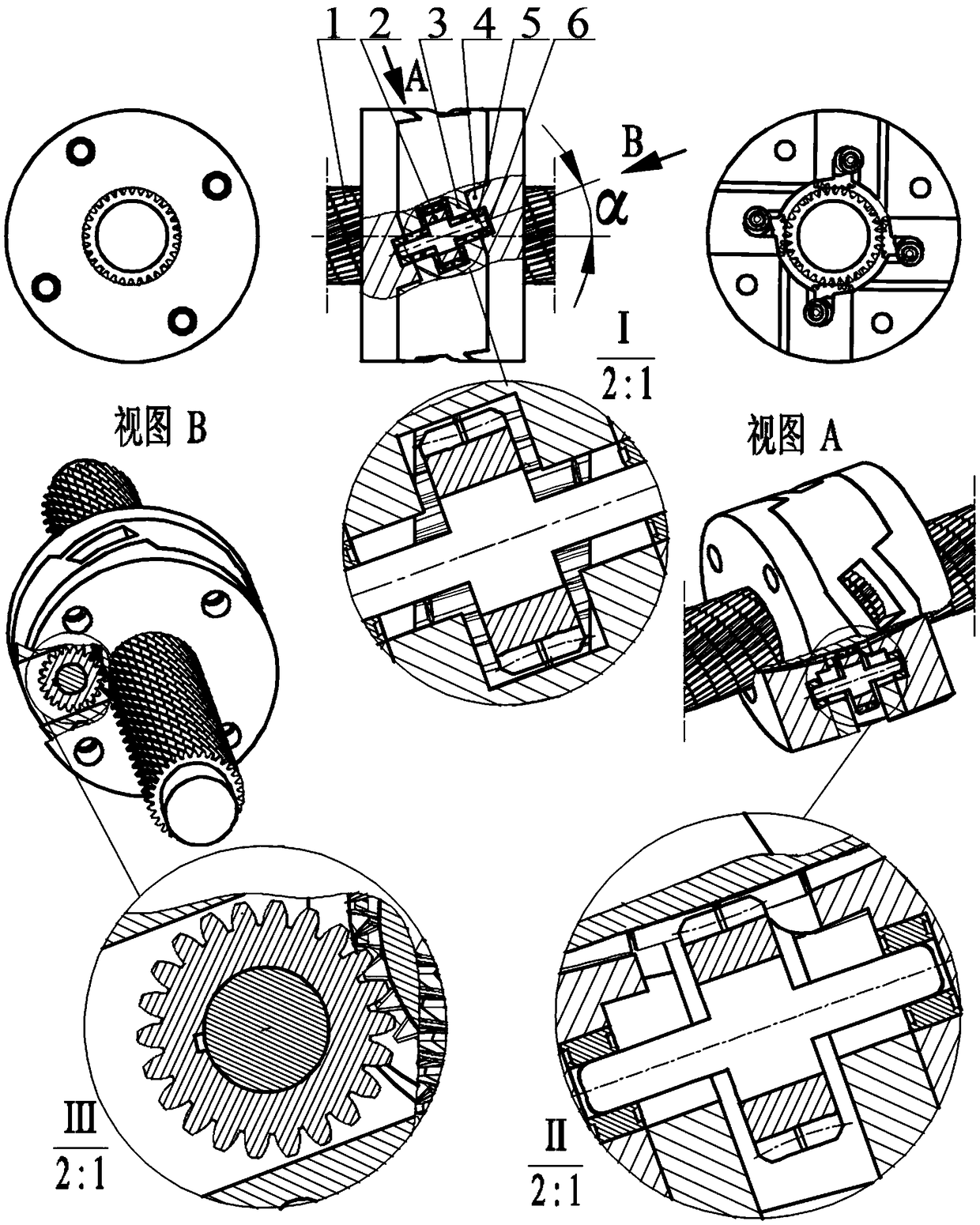
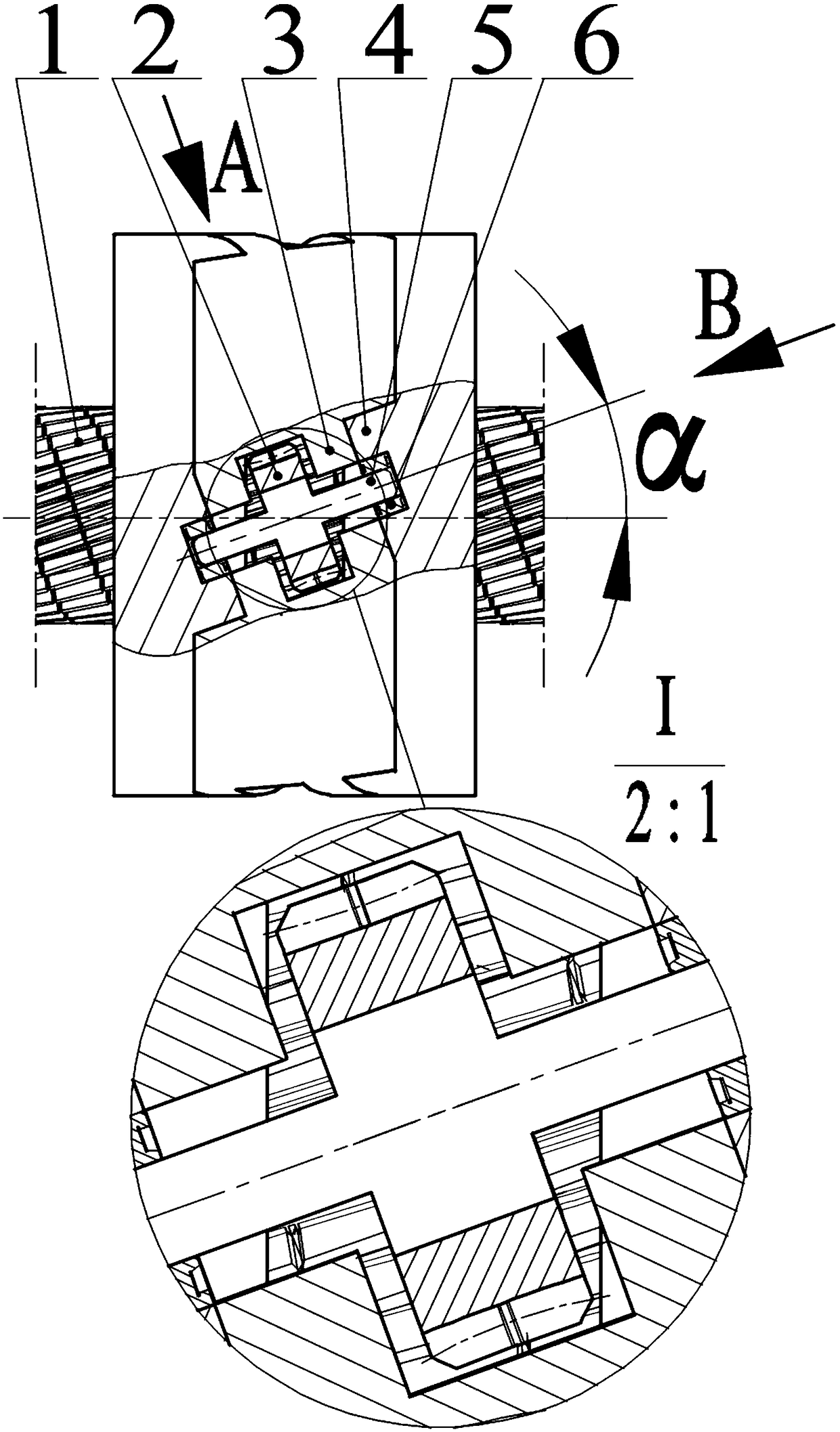
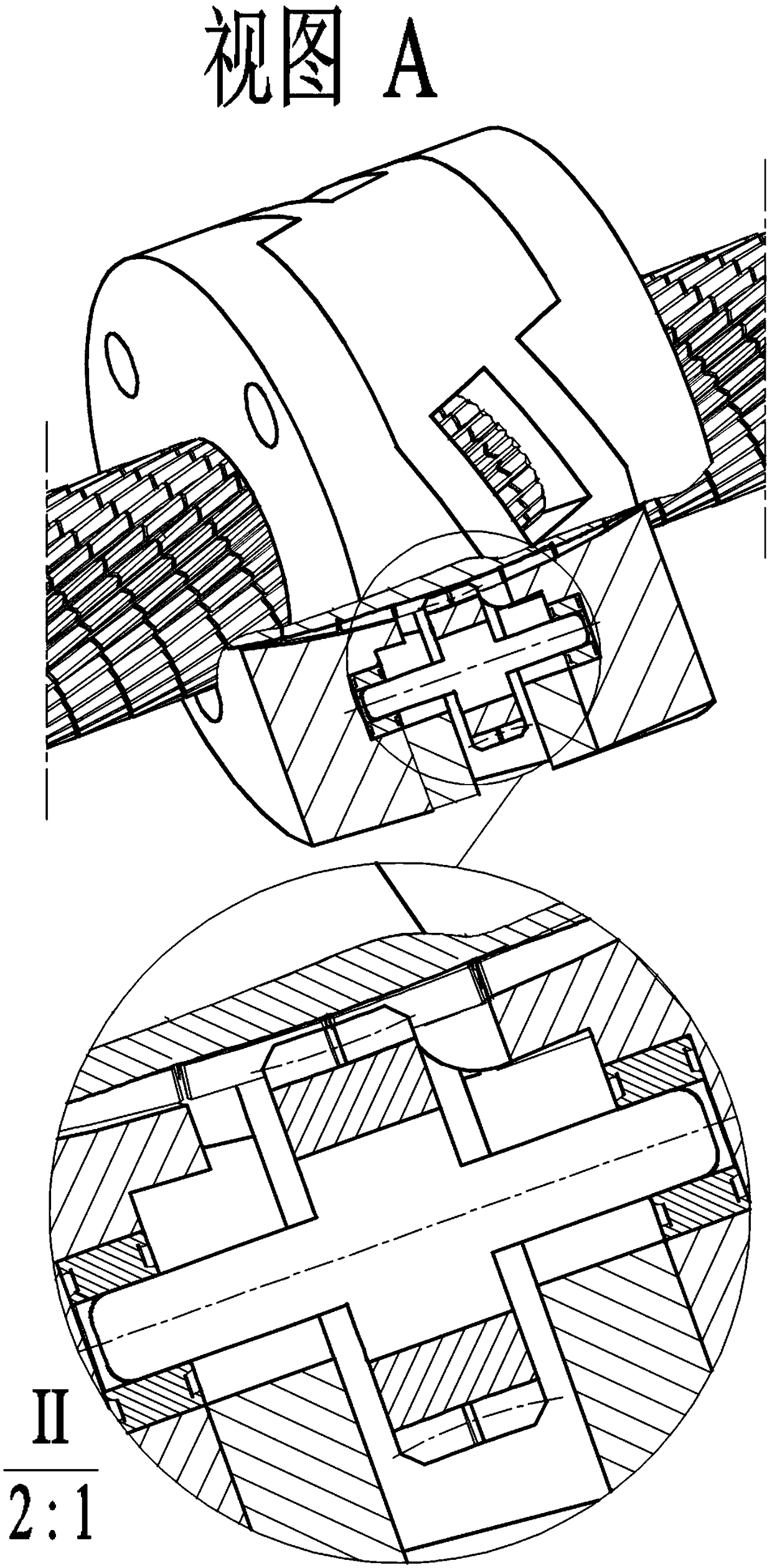
[0025] like Figure 1-Figure 5 Shown: both ends of the sleeve (3) are connected and fixed with the end cover (4), and the worm gear shaft (5) passes through the U-shaped hole on the square hole on the sleeve (3) inclined at an angle α with the axis of the sleeve (3). The groove is installed on the blind hole coaxial with the U-shaped groove on the end cover (4) through a rolling bearing (6).

[0026] like Figure 1-Figure 5 Shown: the new worm gear (2) is fixed on the worm gear shaft (5), the new worm gear (2) meshes with the new helical gear shaft (1), the boss of the new worm gear (2) and the helical teeth of the new helical gear shaft (1) The alignment and fit of the cutouts prevents the original possible relative sliding. The worm gear shaft (5) is fixed on the rolling bearing (6), and the rolling bearing (6) is fixed on the end cover (3). The worm gear shaft (5) together with the The new worm gear (2) is distributed in a circular array of 4 units at equal intervals along ...


PUM


Abstract

The invention discloses a worm gear screw rod which comprises a novel helical tooth shaft, novel worm gears, a sleeve, an end cover, a worm gear shaft, a bearing and the like; the novel helical tooth shaft is a long shaft with helical teeth and is provided with a straight groove cut along a helical line which has the helical angle to be 90 degrees-alpha and is perpendicular to the direction of turning of the helical teeth and a cut with a chamfer to be 60 degrees; the helical teeth have the helical angle of alpha; as for each novel worm gear, a boss with the same section size as the cut is point-processed in a worm gear tooth surface; each worm gear tooth surface is in contact with a tooth surface line of the helical teeth; each boss is aligned at and matched with the cut; the worm gear shaft penetrates through a U-shaped groove formed in the sleeve and is installed on blind holes formed in the end cover through a rolling bearing; and under driving of a motor, the novel worm gears roll on the novel helical tooth shaft along the helical line, and helical transmission is realized by depending on the mechanical biting force. According to the worm gear screw rod, compared with the traditional screw rod, sliding friction is very small and unrelated to the driving force and the axial load, the kinetic helix rise angle can be more greatly increased, the transmission efficiency is higher, and transmission is smoother and more reliable.

Description

technical field [0001] The invention relates to a screw transmission device, in particular to a worm wheel screw. Background technique [0002] The screw is widely used in machine tool equipment. It is a screw transmission device that converts rotary motion into linear motion and torque into thrust. The traditional screw uses the engagement and relative rotation of internal and external threads to transmit force and motion. , due to the existence of sliding friction, and the power of the transmission is also a positive pressure that produces sliding friction resistance, the greater the power and load, the greater the sliding friction resistance, the smaller the thread lift angle of the movement, the lower the transmission efficiency, the faster the wear and the shorter the service life . [0003] In the ball screw, the balls are uncontrolled in the raceway, there is more or less sliding friction, similar to the ordinary screw, the greater the load, the greater the friction ...

Claims


Application Information

Patent Timeline
Patent Type & Authority Patents(China)
IPC IPC(8): F16H1/20F16H55/22
CPCF16H1/203F16H55/22
Inventor 陈永忠
Owner UNIV OF ELECTRONICS SCI & TECH OF CHINA
Why Eureka
Try Eureka