Light weapon sight adjusting instrument
A technology for sights and light weapons, which is applied to sighting devices, weapon accessories, offensive equipment, etc., can solve the problems of "crawling, low adjustment accuracy, complex structure, etc., and achieve easy continuous adjustment, high adjustment accuracy, and large structural rigidity." Effect
- Summary
- Abstract
- Description
- Claims
- Application Information
AI Technical Summary
Problems solved by technology
Method used
Image
Examples
Embodiment 1
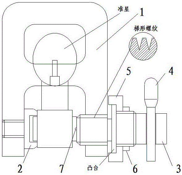
[0020] Such as figure 1 As shown, a light weapon sight adjusting instrument of the present invention is composed of a slot 1, a top iron 2, a push rod 3 and an operating handle 4, wherein the slot 1 is a double-bottomed U-shaped slot; the top iron 2 is threaded Installed on one end of the card slot 1, the ejector rod 3 is installed on the other end of the card slot 1 through the trapezoidal thread, and the pitch of the trapezoidal thread is 3mm; The through hole is used for installing the operating handle 4.
[0021] A boss is provided in the middle of the push rod 3, and the boss and the push rod 3 are an integrated structure. The dial 5 is set on the outside of the boss of the ejector rod 3, and 100 scales are set at equal intervals in the circumferential direction of the dial 5 (combined with the pitch of the trapezoidal thread, each scale corresponds to 0.03mm), and set on the dial 5 0 tick marks. The locking nut 6 is used to lock the dial 5 on the outside of the boss, ...
Embodiment 2
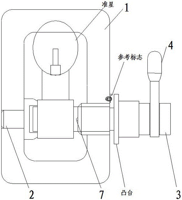
[0028] Such as figure 2 As shown, the structure of the adjuster is basically the same as that of Example 1, and the main structural differences are: (1) The slot 1 is replaced by an O-shaped slot; (2) The pitch of the trapezoidal thread is 4mm; (3) The dial 5 is canceled and the lock nut 6, the scale is directly set on the boss of the ejector rod 3. Since the diameter of the boss is small, 40 scales are set at equal intervals in the circumferential direction of the boss (combined with the pitch of the trapezoidal thread, it can be known that each scale Corresponding to 0.1mm); (4) The top iron 2 is installed on the card slot 1 with a clearance fit, which is more convenient for disassembly and assembly, but the size of the gap should be controlled, otherwise the top iron 2 and the top rod 3 will not be able to Coaxial; (5) Replace the reference line with the reference mark installed on the side of the card slot 1, the reference mark is as image 3 shown.
[0029] When in use...
Embodiment 3
[0031] The structure of the adjuster is basically the same as that of Example 2, and the main structural differences are: (1) The slot 1 is replaced by a double-bottomed U-shaped slot; (2) The pitch of the trapezoidal thread is 5mm; (3) The dial 5 and The lock nut 6 is directly provided with a scale on the boss of the ejector rod 3. Since the diameter of the boss is small, 50 scales are set at equal intervals in the circumferential direction of the boss (combined with the pitch of the trapezoidal thread, each scale corresponds to 0.1mm)
[0032] The method of use is similar to that of Embodiment 1, so it is not repeated here.
PUM
 Abstract
Description
Claims
Application Information
 - R&D
- Intellectual Property
- Life Sciences
- Materials
- Tech Scout
- Unparalleled Data Quality
- Higher Quality Content
- 60% Fewer Hallucinations
Browse by: Latest US Patents, China's latest patents, Technical Efficacy Thesaurus, Application Domain, Technology Topic, Popular Technical Reports.
© 2025 PatSnap. All rights reserved.Legal|Privacy policy|Modern Slavery Act Transparency Statement|Sitemap|About US| Contact US: help@patsnap.com


