Method for assembling metallic guiding needle connector

A guide pin connector and assembly method technology, applied in the field of metal-glass packaging, can solve the problems of low product qualification rate, low assembly accuracy, and low productivity, and achieve high product qualification rate, high assembly accuracy, and low missing assembly rate Effect

Active Publication Date: 2016-12-14
山东云特信息科技有限公司
View PDF3 Cites 0 Cited by
  • Summary
  • Abstract
  • Description
  • Claims
  • Application Information

AI Technical Summary

Problems solved by technology

[0003] The purpose of the present invention is to overcome the shortcomings of the prior art, to seek an assembly method for the metal guide pin connector and the tooling board used, and to solve the problem of sticking after sintering and missing assembly caused by debris left in the existing assembly method. High efficiency, low assembly accuracy, low product qualification rate and low productivity

Method used


Image

  • Method for assembling metallic guiding needle connector
  • Method for assembling metallic guiding needle connector
  • Method for assembling metallic guiding needle connector

Examples


Embodiment 1

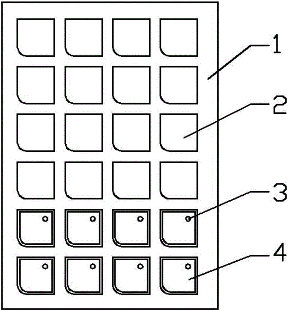
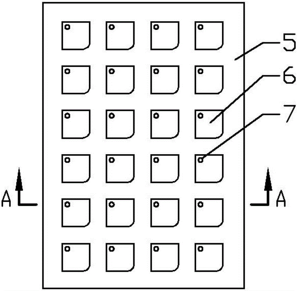
[0022] The metal guide pin connector tooling board involved in this embodiment includes a first tooling board 5 and a second tooling board 9; the first tooling board 5 and the second tooling board 9 are the same length and width as the graphite mold bottom mold 1. The lower surface of the tooling plate 5 is provided with protrusions 6 arranged in an array, and the height of the protrusions 6 is not lower than the difference between the depth of the sintering sink 2 on the bottom mold 1 of the actual graphite mold and the thickness of the metal shell 4. If the height of the protrusions 6 is Too low, the metal shell 4 is prone to shaking during the flipping process of the assembly, the position of the solder hole 3 is offset, each protrusion 6 is provided with a through hole 7, and the upper plate of the first tooling board 5 is provided with 4 cylinders The limit bolt 8 is staggered from the through hole 7, and the height of the limit bolt 8 is 0.3cm; the second tooling board 9 i...

Embodiment 2

[0031] The metal guide pin connector tooling plate involved in this embodiment is equipped with an automatic weighing sensor at the bottom of the cylindrical counterbore 10 on the second tooling plate, the automatic weighing sensor is connected to the central control end, and the central control end is connected to the mechanical arm and embodiment 1. Except for the different tooling plates of the metal guide pin connector, the other structures are the same.

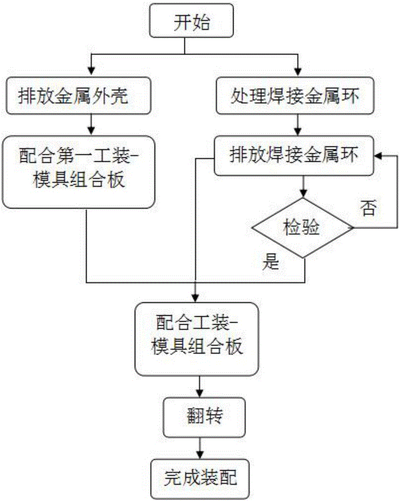
[0032] The method for assembling the metal guide pin connector in this embodiment includes the following steps:

[0033] (1) Discharging the metal shell: Put the bottom mold 1 of the graphite mold into the oscillating sequencer, and then disperse and put more metal guide pin connector metal shell 4 on the bottom mold 1 of the graphite mold than the number of slots in the sintering sink 2. The depth of the sintering sink 2 on the bottom mold 1 of the graphite mold can only discharge a layer of the metal shell 4. The shock sequ...


PUM

PropertyMeasurementUnit
diameteraaaaaaaaaa
thicknessaaaaaaaaaa

Abstract

The invention belongs to the technical field of metal-glass packaging, and relates to a method for assembling a metallic guiding needle connector. The method includes the steps of sorting metal rings, respectively placing a metallic housing of the metallic guiding needle connector and a welding metal ring in a sintering sinking groove of a graphite die block and a cylindrical sinking hole in a second tool plate, fixing a first tool plate and the second tool plate by correspondingly engaging a limiting bolt and a limiting through hole correspondingly connecting the soldering hole in the metallic housing and the cylindrical sinking hole through a through hole in the second tool plate, overturning and shaking the tool plates to automatically complete assembling of the welding metal ring of the metallic guiding needle connector. The method ensures high assembly accuracy, and reduces damage of welding metal rings during a manual clamping process. Remaining chips on a graphite die are less, Bead splashing and sticking phenomenon after sintering can be reduced. The method has the advantages of low neglected packing rate, high assembly precision and product qualified rate, reasonable assembly process and good economic returns. The method is applicable to mass production.

Description

Technical field [0001] The invention belongs to the technical field of metal-glass packaging, and relates to a method for assembling a metal guide pin connector. The metal shell of the metal guide pin connector and the welding metal ring are respectively placed on the bottom mold of a graphite mold and a second tooling plate through metal The shell solder hole, the through hole and the cylindrical counterbore are connected correspondingly in sequence, and the assembly of the metal guide pin connector parts is automatically realized. Background technique [0002] As one of the key components of integrated circuits, metal-glass encapsulated metal guide pin connectors can meet the requirements of high-power circuits, high and low frequency circuits and various hybrid integrated circuits in aerospace, aviation and other fields. They are mainly used for circuit support, electrical Signal transmission, heat dissipation, sealing and chemical protection, etc., effectively improve the rel...

Claims


Application Information

Patent Timeline
Patent Type & Authority Applications(China)
IPC IPC(8): H01R43/18
CPCH01R43/18
Inventor 张云飞王舜华曹侠
Owner 山东云特信息科技有限公司
Why Eureka
Try Eureka