
Electronic stethoscope based on MEMS technology

An electronic and stethoscope technology, applied in stethoscopes, contact microphone transducers, hearing devices with active noise cancellation, etc., can solve problems such as inability to display heart rate in real time, no amplification, and inability for doctors to make timely and accurate diagnoses, etc. , to achieve the effect of convenient and accurate auscultation process, improvement of sound pickup sensitivity, practicality and convenience

Inactive Publication Date: 2016-12-21
苏州中盛纳米科技有限公司
View PDF5 Cites 11 Cited by
  • Summary
  • Abstract
  • Description
  • Claims
  • Application Information

AI Technical Summary

Problems solved by technology

[0002] As an essential medical tool for doctors, the stethoscope plays an important role in the diagnosis of cardiovascular and respiratory diseases. The traditional stethoscope is composed of a resonant plate, a resonant cavity and a sound conduit. The disadvantage is that it has no amplification effect and the sound It is relatively weak, and it is also greatly affected by environmental noise, and there is no LCD screen to display the heart rate in real time
Doctors need to read the number of heartbeats based on watches or other timing tools and then convert them into heart rates. These shortcomings will cause doctors to be unable to make timely and accurate diagnoses in some cases
The Chinese patent application with the patent application number CN201510589217.5 discloses a "visual electronic stethoscope based on MEMS acoustic sensor". However, the electronic stethoscope is not equipped with a stethoscope tube, so it can only store the heartbeat signal for a certain period of time, display the waveform through the upper computer on the computer side, and judge the patient's condition from the waveform situation. In treatment, auscultation is still an important means for doctors to judge the patient's condition

Method used


Image

  • Electronic stethoscope based on MEMS technology
  • Electronic stethoscope based on MEMS technology
  • Electronic stethoscope based on MEMS technology

Examples


Embodiment Construction

[0032] The specific embodiment of the present invention is further described below in conjunction with accompanying drawing:

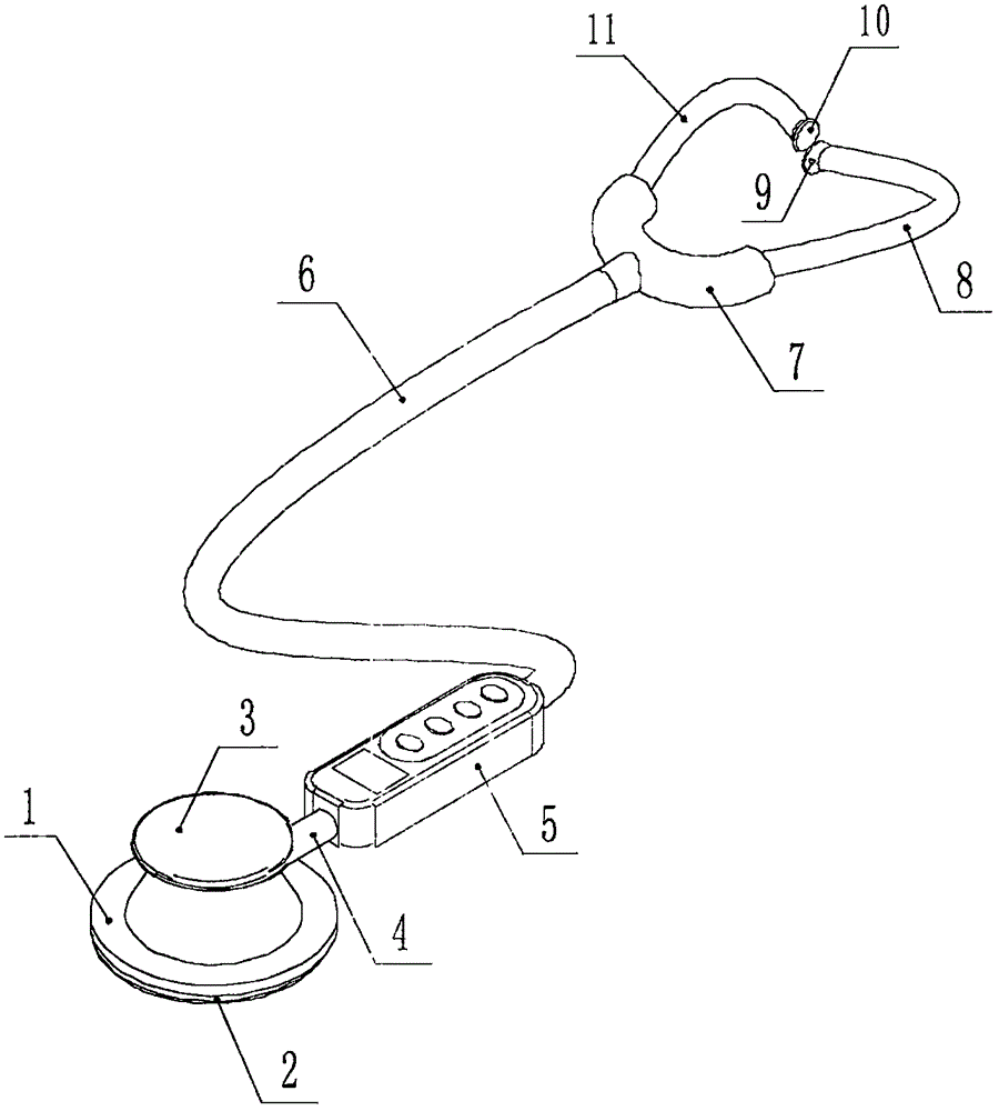
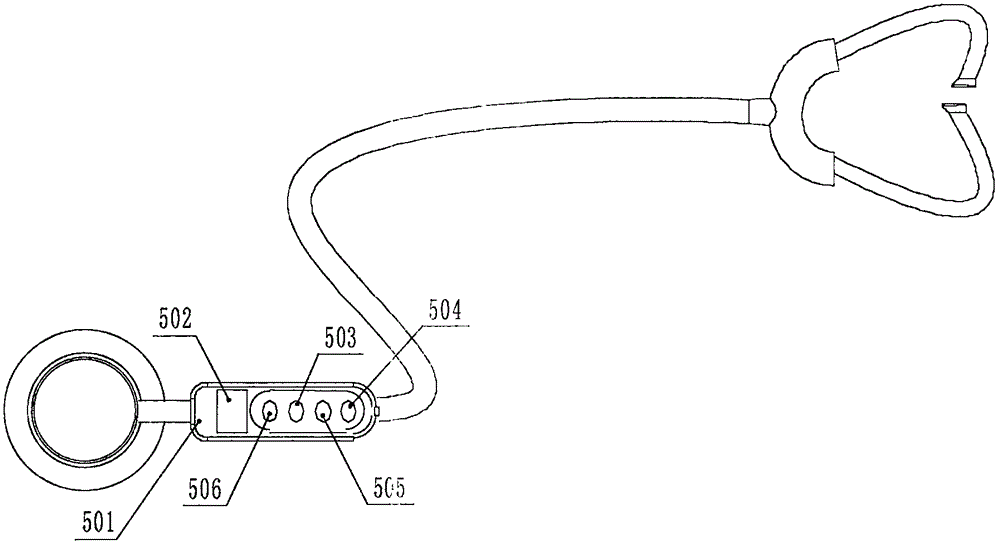
[0033]An electronic stethoscope based on MEMS technology, including: pickup head 1, sound-permeable rubber cap 2, pickup head cover 3, hollow conduit 4, hand-held support tube 5, leather tube 6, bifurcated tube 7, right Binaural catheter 8, right earphone head 9, left earphone head 10, left binaural catheter 11 and cantilever beam-cilia microstructure 12, described pickup head loam cake 3 is installed on the pickup head 1 by threaded connection, so The bottom surface of the pickup head 1 is provided with an annular slot, the sound-permeable rubber cap 2 is fixedly installed in the ring slot of the pickup head 1 by polyurethane glue, and the pickup head 1 is provided with a cavity , the cantilever-cilia microstructure 12 is installed in the cavity of the pickup head 1, one end of the hollow conduit 4 is connected with the pickup head 1, and the other en...


PUM


Abstract

The invention discloses an electronic stethoscope based on the MEMS technology. According to the electronic stethoscope, a pickup head upper cover is mounted on a pickup head through thread connection, an annular clamp groove is formed in the bottom surface of the pickup head, a acoustically transparent rubber cap is fixedly mounted in the annular clamp groove of the pickup head through polyurethane glue, a cavity is arranged in the pickup head, a cantilever beam-cilium type microstructure is mounted in the cavity of the pickup head, one end of a hollow conduit is connected with the pickup head, the other end of the hollow conduit is connected with a hand-holding support pipe, the hand-holding support pipe is connected with a bifurcated pipe through a leather hose, a right binaural conduit and a left binaural conduit are mounted on the bifurcated pipe, a right earphone head is mounted on the right binaural conduit, and a left earphone head is mounted on the left binaural conduit. According to the electronic stethoscope, the acoustic microstructural sensor processed based on the MEMS technology and having high sensitivity is taken as the pickup device or picking up heart sound signals, and the electronic stethoscope has the advantages that the sensitivity is high, the heart rate is displayed in real time, the auscultation is clear, the waveforms can be displayed at the computer end, etc.

Description

technical field [0001] The invention belongs to the technical field of intelligent medical devices, in particular to an electronic stethoscope based on MEMS technology. Background technique [0002] As an essential medical tool for doctors, the stethoscope plays an important role in the diagnosis of cardiovascular and respiratory diseases. The traditional stethoscope is composed of a resonant plate, a resonant cavity and a sound conduit. The disadvantage is that it has no amplification effect and the sound It is relatively weak, and it is also greatly affected by environmental noise, and there is no LCD screen to display the heart rate in real time. Doctors need to read the number of heartbeats based on watches or other timing tools and then convert them into heart rates. These shortcomings will cause doctors to be unable to make timely and accurate diagnoses in some cases. The Chinese patent application with the patent application number CN201510589217.5 discloses a "visua...

Claims


Application Information

Patent Timeline
IPC IPC(8): A61B7/04A61B5/0245H04R1/46
CPCA61B7/04A61B5/02444A61B5/0245A61B5/7225A61B5/7445H04R1/46H04R2201/003H04R2460/01
Inventor 郭涛张国军曾瑞张斌珍韩建军郝晓康
Owner 苏州中盛纳米科技有限公司
Learn More