
A device for ultrasonic examination

A technology of ultrasonic inspection and lifting rod, which is applied in the field of medical equipment, can solve the problems of increased labor intensity, long duration, and easy-to-fall diseases, and achieve the effect of reducing labor intensity and simple structure

Inactive Publication Date: 2019-03-05
刘浩
View PDF9 Cites 0 Cited by
  • Summary
  • Abstract
  • Description
  • Claims
  • Application Information

AI Technical Summary

Problems solved by technology

[0003] In the process of comprehensive examination, patients need to have a variety of postures, and medical staff have a large range of activities, a wide range, and a long duration. Doctors’ arms and wrists need to bear the pressure of the probe for a long time, without rest, and it is easy to fall sick
[0004] Especially during the standing examination, if the patient stands on the bed, the medical staff will perform the examination. Due to the large difference in the height of the patient, some positions of the medical staff cannot be effectively inspected; strength

Method used


Image

  • A device for ultrasonic examination
  • A device for ultrasonic examination
  • A device for ultrasonic examination

Examples


Embodiment 1

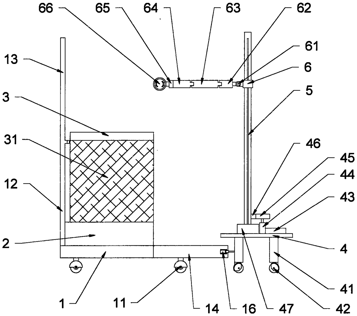
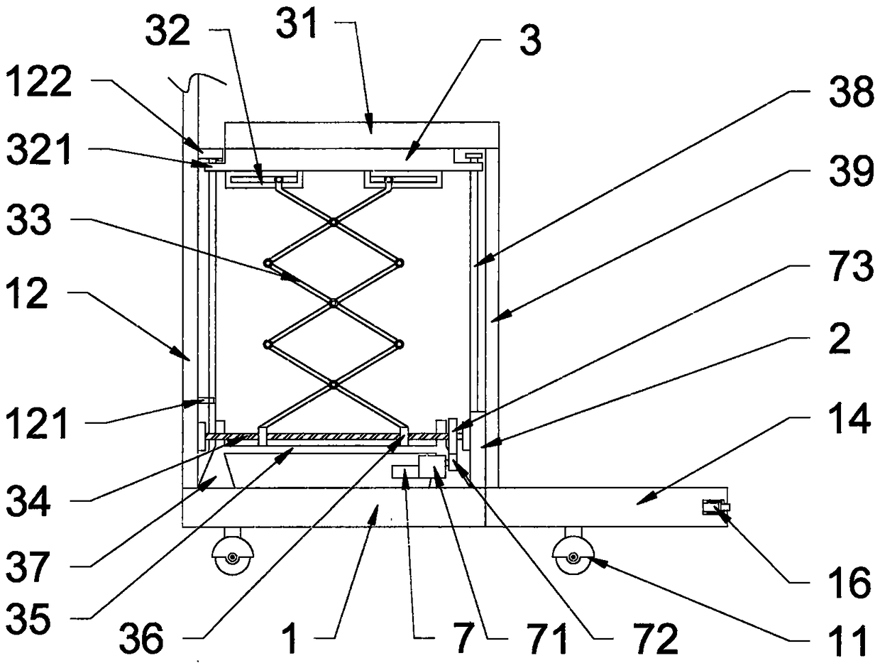
[0032] according to Figures 1 to 6 The ultrasonic inspection device shown includes a lift chair, a lift rod, a mechanical arm, and a controller. The lift chair includes a base 1, a fixed side bracket 12, a driving mechanism, a lifting frame, and a support plate 3. A first universal wheel 11 is provided, a fixed side bracket 12 is provided on one side of the base 1, an isolation plate 2 is provided on the base 1, a driving mechanism is provided on the base 1, and the driving mechanism includes a first support Seat 37, the first slide rail 35, the first lead screw 34, the first servo motor 7, the first slide rail 35 and the first lead screw 34 are parallel to each other, the output end of the first servo motor 7 is connected to the first The reduction box 71 is connected, and the output end of the first reduction box 71 is provided with a first driving gear 72, and the first driving gear 72 is engaged with the first driven gear 73, and the first driven gear 73 drives the first ...

Embodiment 2

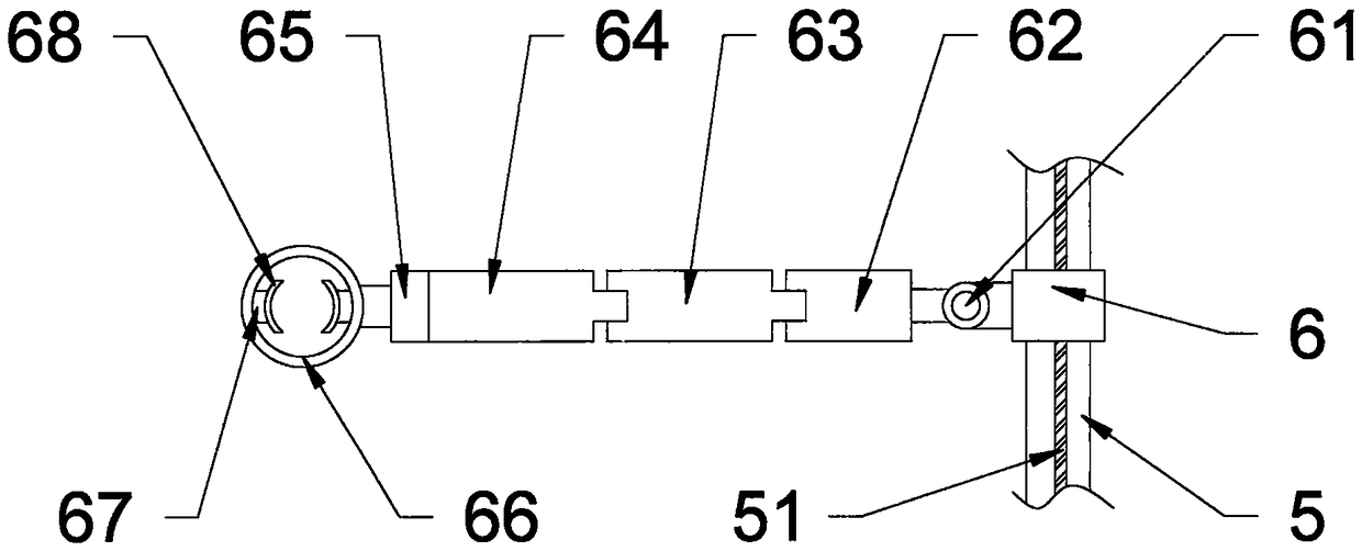
[0050] Such as Figures 1 to 6 In the ultrasonic inspection device shown, on the basis of Embodiment 1, a second slide rail is provided in the support ring 66, a slip ring 661 is provided in the second slide rail, and two elastic members 67 are arranged symmetrically. Inside the slip ring 661 , the elastic member 67 is provided with a clamping member 68 , which is detachably connected to the elastic member 67 , and the slip ring 661 can rotate in the supporting ring 66 to facilitate the rotation of the probe.


PUM


Abstract

The invention relates to a device for ultrasonic inspection. The device comprises a lifting chair, a lifting rod, a mechanical arm and a controller. The lifting chair comprises a base, a fixing-side supporting frame, a driving mechanism, a lifting frame and a supporting plate. Guiding grooves are formed in the lower surface of the supporting plate, and guiding sliding blocks are arranged at the top ends of supporting rods on most-top layers of two shearing assemblies, and are assembled in the guiding grooves; the lifting rod comprises a second supporting base, a second lead screw and a second servo motor, a guiding sleeve is arranged outside the second lead screw, a lifting sleeve is arranged outside the guiding sleeve, and the mechanical arm is arranged on the lifting sleeve; the mechanical arm comprises a first joint, a second joint, a third joint, a supporting ring and a clamping piece, a first servo motor and the second servo motor are electrically connected with the controller, and a lifting-chair control switch and a lifting-rod control switch are arranged on the controller. The device has the advantages that the structure is simple, the standing height of patients is automatically adjusted, a probe can be supported, and the labor intensity of medical workers can be effectively reduced.

Description

technical field [0001] The invention relates to the field of medical instruments, in particular to an ultrasonic inspection device. Background technique [0002] The application of ultrasound technology in modern medicine is very common. Ultrasound plays an important role in the examination and diagnosis of the disease. The clinical significance of Doppler ultrasound examination on peripheral blood vessels is becoming more and more important. Doppler ultrasound examination is non-invasive, non-radiative, Fast, cheap, and has unique advantages compared with angiography. Doppler can check the neck veins, upper limb blood vessels, and lower limb blood vessels. The examination can be carried out in a sitting position or in a position where the head of the bed is too high by 30 degrees and the head is high and the feet are low. When examining the popliteal artery and its distal veins, it is best to use a standing position, mainly to allow the veins of the lower extremities to be ...

Claims


Application Information

Patent Timeline
Patent Type & Authority Patents(China)
IPC IPC(8): A61B8/00
CPCA61B8/40A61B8/44A61B8/4444
Inventor 刘浩
Owner 刘浩
Learn More