A continuous transmission quasi-non-diffracting wave microwave reactor

A microwave reactor, non-diffraction technology, applied in microwave heating, chemical instruments and methods, chemical/physical/physical-chemical processes of applying energy, etc., can solve difficult-to-process materials, insufficient utilization of microwave energy, slow processing speed, etc. problems, to achieve the effect of reducing the demand for output power, good reaction uniformity, and improving reaction efficiency

Active Publication Date: 2018-07-27
UNIV OF ELECTRONICS SCI & TECH OF CHINA
View PDF3 Cites 0 Cited by
  • Summary
  • Abstract
  • Description
  • Claims
  • Application Information

AI Technical Summary

Problems solved by technology

[0002] In recent years, high-power microwave reactors have been widely used in heating, medical treatment, drying, coating, environmental protection, auxiliary extraction and other occasions, and achieved good results; however, reactors for solid material processing still face many problems
First of all, the application of microwave energy has entered the stage of large-scale industrialization, and the microwave reactor for single treatment is no longer suitable for the needs of industrialized continuous production; as in the patent document whose publication number is CN102946655A, it is necessary to manually remove the material every time for solid materials. Put it into the reactor, take it out manually after the reaction is completed, low efficiency, cumbersome operation, and poor safety
Secondly, with the deepening of research on the application of microwave energy, a variety of continuous transmission microwave reactors have been applied to various industrial productions, such as: rectangular waveguide reactors, ridge waveguide reactors, and flat waveguide reactors; They all belong to single-mode resonant microwave reactors, and to a certain extent, there are shortcomings such as small capacity, uneven field distribution, insufficient utilization of microwave energy, and slow processing speed; although circular waveguide reactors solve these problems to a certain extent , but it is still a single-mode resonant type with a small capacity and can only process a small number of small samples, which cannot meet the urgent needs of continuous processing of large-volume materials; for example, a pipeline-type industrial microwave heating is disclosed in the patent document with the publication number CN105338677A The microwave feeding device is evenly arranged outside the pipeline structure. By changing the structure of the microwave heating cavity, the mode of microwave industrial heating is fundamentally changed and the heating efficiency is improved. However, it still uses the waveguide feeding form for heating and requires multiple Microwave source is realized, the feeding structure is complicated, and the material filling operation is troublesome, and it is difficult to process larger materials
[0003] Aiming at the application requirements of large-scale microwave reactors, a non-resonant microwave reaction chamber is proposed, and the volume of the reaction chamber is greatly increased; the principle is to directly feed power into the large-scale reaction chamber through reasonable design, and generate various field modes, so that the inside of the chamber The field is concentrated in a specific area, and at the same time, conduits, conveyor belts, etc. are placed here to make the objects to be processed pass through the field concentration area at a continuous and uniform speed, so as to achieve the purpose of heating or increasing the chemical reaction rate; Poor performance, low reaction efficiency, high energy consumption, difficult to process solids, etc.
For example, the patent document with publication number CN104667849A adopts serpentine waveguide feeding, which can only continuously process gas and liquid samples. Devices are required to absorb unradiated energy, resulting in waste

Method used


Image

  • A continuous transmission quasi-non-diffracting wave microwave reactor
  • A continuous transmission quasi-non-diffracting wave microwave reactor
  • A continuous transmission quasi-non-diffracting wave microwave reactor

Examples


Embodiment

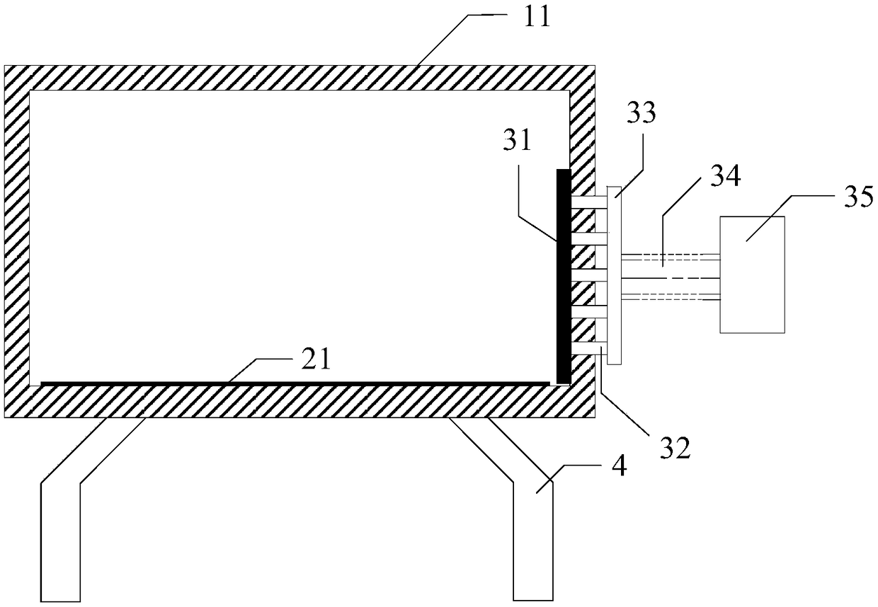
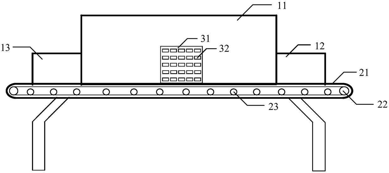
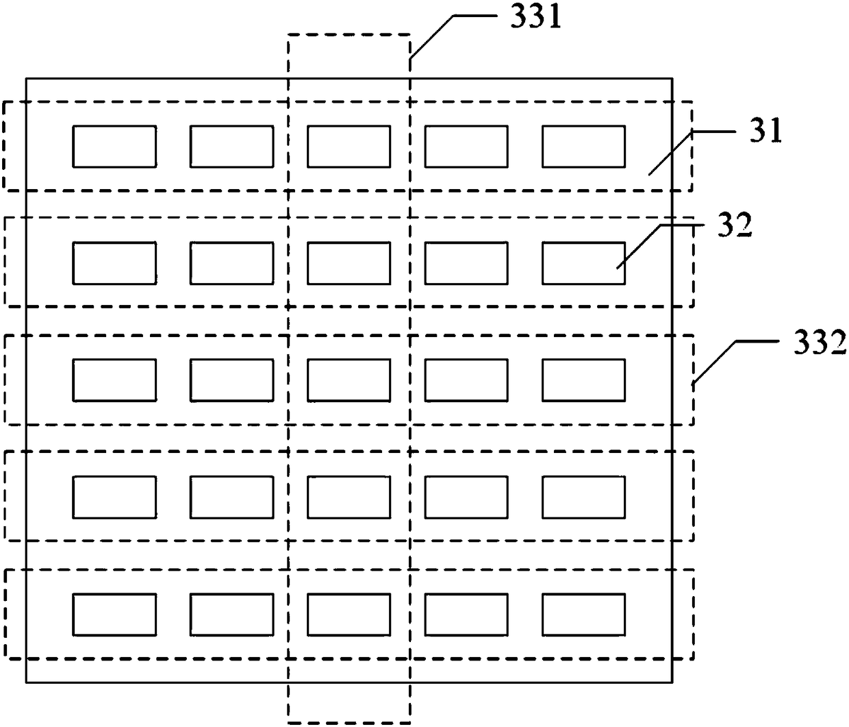
[0029]The present embodiment provides a continuous transmission quasi-non-diffracting wave microwave reactor, including a reaction device, a transmission device, a feeder and a support device; it is characterized in that the reaction device includes a cubic hollow metal cavity (11), which is arranged on a metal A cubic hollow metal inlet (12) extending outwards on one end surface of the cavity is not closed at both ends, and a corresponding outlet (13) of the same shape and size is arranged on the other end surface, and the inlet (12) and the outlet A thin absorbing material is attached to the inner wall of the mouth (13) to prevent microwave leakage; the transmission device includes: a conveyor belt (21), an adjustable speed motor and a power roller (22) and a supporting roller (23), and the conveyor belt passes through the metal cavity (11), the feed port (12) and the discharge port (13) are in contact with the bottom, the lower part of the conveyor belt is supported by a num...


PUM


Abstract

The invention belongs to the field of microwave energy application devices, and provides a continuous transmission type quasi-non-diffraction wave microwave reactor, including a reaction device, a transmission device, a feeding device and a supporting device; the feeding device includes a radiator, a feeding waveguide, and a power distribution device. and phase shifter, coaxial transmission line and microwave source; the microwave source is connected to the input end of the power distribution and phase shifter through the coaxial transmission line, and the output end of the power distribution and phase shifter is connected to several feeder waveguides, and the feeder waveguide passes through The radiator is connected to the radiator through the metal cavity. The radiator is located at the middle and lower part of the back of the metal cavity. The radiator is provided with a rectangular radiation port of the same size as the feed waveguide. The present invention adopts the way of multi-feeder feed-in to generate non-diffraction wave to irradiate the reactant, so as to improve the reaction efficiency, speed up the reaction speed, improve the uniformity of the reaction and save energy, and combine it with the continuous transmission production line, and apply it on a large scale In industrial production.

Description

technical background [0001] The invention belongs to the field of microwave energy application devices, in particular to a continuous transmission type quasi non-diffraction wave microwave reactor. Background technique [0002] In recent years, high-power microwave reactors have been widely used in heating, medical treatment, drying, coating, environmental protection, auxiliary extraction, etc., and achieved good results; however, reactors for solid material processing still face many problems. First of all, the application of microwave energy has entered the stage of large-scale industrialization, and the microwave reactor for single treatment is no longer suitable for the needs of industrialized continuous production; as in the patent document whose publication number is CN102946655A, it is necessary to manually remove the material every time for solid materials. Put it into the reactor and take it out manually after the reaction is completed, which is inefficient, cumbers...

Claims


Application Information

Patent Timeline
Patent Type & Authority Patents(China)
IPC IPC(8): B01J19/12H05B6/70H05B6/76
CPCB01J19/126B01J2219/1239B01J2219/1242B01J2219/1281H05B6/701H05B6/76
Inventor 程钰间钟熠辰薛飞宣智杰樊勇张波林先其张永鸿赵明华
Owner UNIV OF ELECTRONICS SCI & TECH OF CHINA
Why Eureka
Try Eureka