
Large stroke high speed electric tapping machine

A tapping machine and large-stroke technology, applied in the field of tapping machines, can solve problems such as large tapping stroke, fast tapping speed, and complex structure, and achieve the effects of guaranteed machining accuracy, improved tapping accuracy, and simple operation

Active Publication Date: 2018-09-07
邻水县川邻机械制造有限公司
View PDF8 Cites 0 Cited by
  • Summary
  • Abstract
  • Description
  • Claims
  • Application Information

AI Technical Summary

Problems solved by technology

However, the spindle part of this type of tapping machine has many parts and complex structure, which relatively affects the stability and smoothness of the spindle movement.
The disadvantage is that the precision of tapping is not high, the effect is slow, and the stroke is short. The tapping stroke is generally only 50mm, which is usually only suitable for thread hole processing on one plane.
[0004] Due to the threaded hole, especially the deep hole tapping with a hole depth greater than 50mm, there is a long-term unresolved contradiction between the large tapping stroke and the fast tapping speed. intractable problem

Method used


Image

  • Large stroke high speed electric tapping machine
  • Large stroke high speed electric tapping machine
  • Large stroke high speed electric tapping machine

Examples


Embodiment Construction

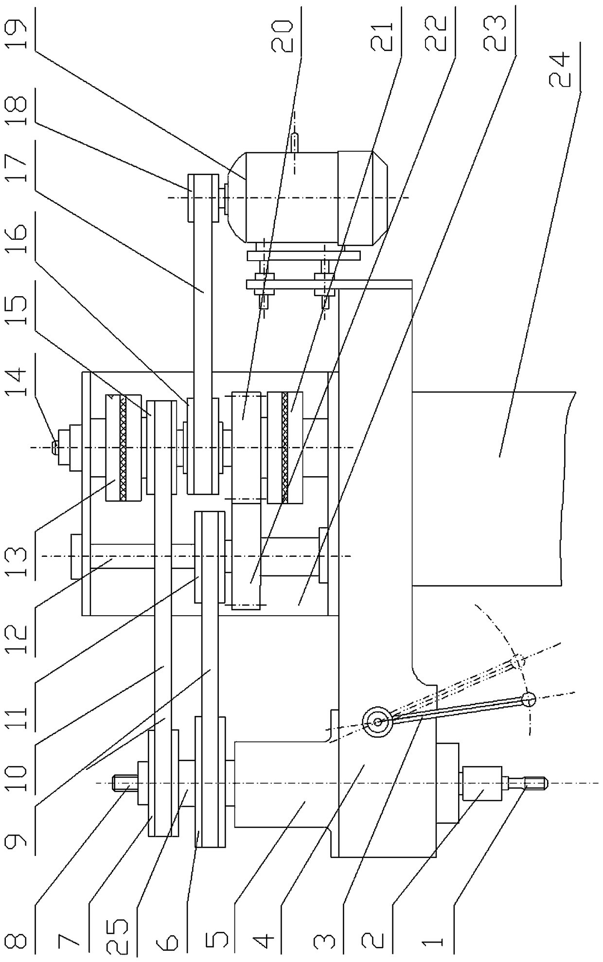
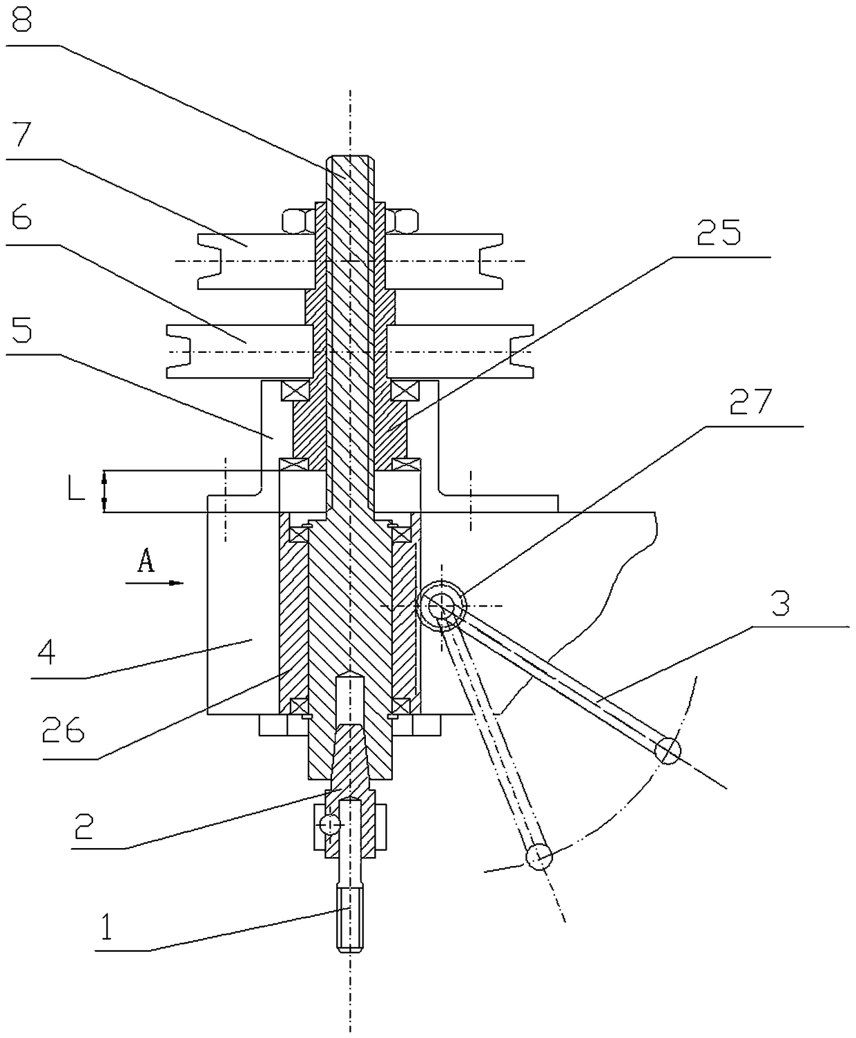
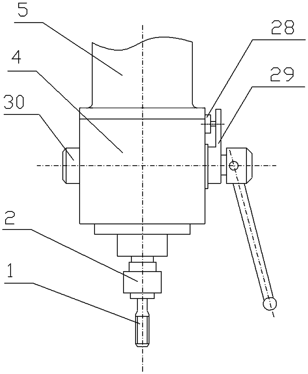
[0024] see Figure 1 to Figure 3, an embodiment of a large-stroke high-speed electric tapping machine, the large-stroke high-speed electric tapping machine includes a machine base with a column and a worktable, and a headstock 4 is installed on the column 24 of the machine base, and the headstock 4 is in the form of The beam shape is installed on the column 24, and the headstock 4 can be installed on the column 24 in a fixed manner, or can be installed on the column 24 in a controllable lifting manner, and the controllable lifting method adopts the conventional lifting movement of the machine tool The structural assembly is enough, so that the working height adjustment of the Z coordinate direction for different workpieces can be realized. The workbench (not shown) can be set as a cross slide, so that the workpiece to be processed can move quickly and accurately in the coordinates X and Y directions through the cross slide, which is convenient for sequentially tapping holes in...


PUM


Abstract

The invention provides a large-stroke and high-speed electric tapper. A clutch transmission case is arranged between a feed machine head of a machine head base and an electric motor. A clutch rotating shaft and a transmission shaft are vertically arranged in the case side by side. The clutch rotating shaft is connected with the electric motor through belt wheel transmission. Two electromagnetic clutches are arranged at the upper end and the lower end of the clutch rotating shaft correspondingly. A first transfer belt wheel and a reversing driving gear which are in sliding fit with the clutch rotating shaft are connected with armatures of the two electromagnetic clutches correspondingly. A second transfer belt wheel and a reversing driven gear engaged with the reversing driving gear are fixed to the transmission shaft. An inner spline sleeve is supported in the head end of the machine head base. Two driven belt wheels on the inner spline sleeve are connected with the first transfer belt wheel and the second transfer belt wheel through conveyor belts correspondingly. The upper section of a main shaft of the feed machine head is a spline section and matched with a spline of the inner spline sleeve. The lower section of the main shaft of the feed machine head is a cylindrical section which is positioned together with a stroke sleeve through a shaft, and the lower section is in sliding fit with the stroke sleeve. A rack is arranged on the outer wall of the stroke sleeve and engaged with a gear shaft. A switch thumbing fork installed on the gear shaft corresponds to a stroke switch.

Description

technical field [0001] The invention relates to the field of tapping machines, in particular to a large-stroke high-speed electric tapping machine. Background technique [0002] At present, the forward rotation or reverse rotation of the main shaft of the common electric tapping machine usually uses a bidirectional motor, and the forward and reverse rotation of the bidirectional motor is controlled by an AC contactor or a reverse switch to realize the main shaft rotation, so as to achieve tapping or unwinding. The purpose of the bidirectional motor is that there will be an instantaneous current increase and a large commutation inertial vibration during the forward and reverse commutation process of the bidirectional motor. Once the motor speed is fast, the motor will be burned. Therefore, the tapping of this electric tapping machine The speed usually does not exceed 300 rpm, and its working efficiency is low, so it is generally only suitable for small parts processing; and w...

Claims


Application Information

Patent Timeline
Patent Type & Authority Patents(China)
IPC IPC(8): B23G3/00
CPCB23G3/00
Inventor 程云生
Owner 邻水县川邻机械制造有限公司
Learn More