Improved dye vat

A technology for dyeing vats and vats, applied in the field of dyeing, which can solve the problems of low cleaning efficiency, high labor costs, and sticking to the inner wall of the dyeing vat, and achieve the effects of avoiding secondary pollution, high cleaning efficiency, and preventing re-diffusion

Active Publication Date: 2016-12-21
浙江华昌新材料股份有限公司
View PDF5 Cites 0 Cited by
  • Summary
  • Abstract
  • Description
  • Claims
  • Application Information

AI Technical Summary

Problems solved by technology

[0003] Tie-dyeing is a dyeing method in which the fabric is partially ligated during dyeing so that it cannot be colored. It is one of the traditional Chinese manual dyeing techniques. Reactive dyes are the main dyes in tie-dyeing. In order to improve the efficiency of tie-dyeing, continuous dyeing is generally used at present. In continuous dyeing, the concentration of dye in the dye liquor will decrease during the dyeing process, so it is necessary to add dye, but the dye will stick to the inner wall of the dye vat during the dyeing process, and the dye may be re-mixed into the dye liquor during the dye liquor flow Therefore, in order to ensure the accuracy of the dye concentration in the dye solution, it is necessary to clean the dye on the inner wall of the dye vat before adding the dye. Cleaning, the cleaning efficiency is low by this method, and the labor cost is high; the sewage generated during the dyeing process needs to be treated before being discharged. The traditional sewage treatment is only a simple treatment of the primary sewage, and there is no secondary advanced sewage treatment device

Method used


Image

  • Improved dye vat
  • Improved dye vat
  • Improved dye vat

Examples


Embodiment Construction

[0029] The following are specific embodiments of the present invention and in conjunction with the accompanying drawings, the technical solutions of the present invention are further described, but the present invention is not limited to these embodiments.

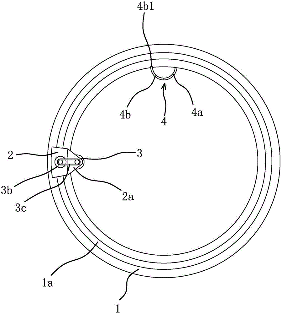
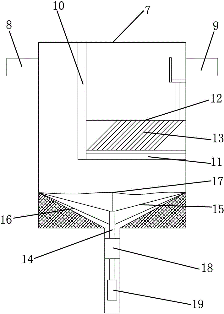
[0030] Such as figure 1 , figure 2 As shown, an improved dye vat includes a cylindrical cylinder body 1, a circular guide rail 1a is fixed on the open end face of the cylinder body 1, and a slider 2 is provided on the guide rail 1a, and the slider 2 can move along the guide rail 1a. Sliding, the slider 2 is provided with an extension part 2a extending to the inside of the cylinder body 1, and the extension part 2a is rotatably connected with a cleaning roller 3, the cleaning roller 3 is vertically arranged and the peripheral surface of the cleaning roller 3 is attached to the inner wall of the cylinder body 1 Rely, the slider 2 is provided with a rotating motor 3b that drives the cleaning roller 3 to rotate. The upper e...


PUM

PropertyMeasurementUnit
thicknessaaaaaaaaaa
diameteraaaaaaaaaa
thicknessaaaaaaaaaa

Abstract

The invention provides an improved dye vat, and belongs to the technical field of dyeing. The improved dye vat solves the problems that in the prior art, a dye vat can not be automatically cleaned, and dye liquor can not be automatically treated. The improved dye vat comprises a cylindrical vat body. A circular guide rail is fixed to the end face of the open end of the vat body, a sliding block is arranged on the guide rail and can slide along the guide rail, an extension part extending to the inner side of the vat body is arranged on the sliding block, a cleaning roller is rotationally connected to the extension part and is vertically arranged, the circumferential surface of the cleaning roller is attached to the inner wall of the vat body, and a rotating motor driving the cleaning roller to rotate is arranged on the sliding block. The vat body is further connected with a flocculation basin, the flocculation basin comprises a sedimentation basin, a water inlet pipe is arranged at the top of one side of the sedimentation basin, a water outlet pipe is arranged at the top of the other side of the sedimentation basin, the water inlet pipe is communicated with the vat body through a first water pipe, a sedimentator is arranged in the sedimentation basin, and a water inlet partition plate is vertically arranged in the sedimentation basin. The improved dye vat has the advantages that the dye vat can be automatically cleaned, and dye liquor can be automatically treated.

Description

technical field [0001] The invention belongs to the technical field of dyeing and relates to an improved dye vat. Background technique [0002] The dye vat is the main tool used for cloth dyeing. When dyeing, the dyeing solution is added to the dye vat, and then the cloth to be dyed is added to achieve dyeing. [0003] Tie-dyeing is a dyeing method in which the fabric is partially ligated during dyeing so that it cannot be colored. It is one of the traditional Chinese manual dyeing techniques. Reactive dyes are the main dyes in tie-dyeing. In order to improve the efficiency of tie-dyeing, continuous dyeing is generally used at present. In continuous dyeing, the concentration of dye in the dye liquor will decrease during the dyeing process, so it is necessary to add dye, but the dye will stick to the inner wall of the dye vat during the dyeing process, and the dye may be re-mixed into the dye liquor during the dye liquor flow Therefore, in order to ensure the accuracy of the...

Claims


Application Information

Patent Timeline
Patent Type & Authority Applications(China)
IPC IPC(8): D06B23/14D06B23/20C02F9/14C02F103/30
CPCC02F1/001C02F1/50C02F1/52C02F3/02C02F9/00C02F2103/30C02F2301/08C02F2303/14D06B23/14D06B23/20D06B2700/36
Inventor 戚小华
Owner 浙江华昌新材料股份有限公司
Why Eureka
Try Eureka