Fastening connection assembly and structure, mounting and dismounting method, crankshaft connecting-rod mechanism, rail structure, bone connecting device and bone connection method

A technology for fastening connections and components, which is applied in the direction of connecting components, threaded fasteners, locking fasteners, etc., can solve the problems of no use value, and the difficulty of the anti-rotation sleeve, and achieves quick removal, reduced size, and reduced cost effect

Pending Publication Date: 2016-12-21
杨东佐
View PDF18 Cites 15 Cited by
  • Summary
  • Abstract
  • Description
  • Claims
  • Application Information

AI Technical Summary

Problems solved by technology

[0013] Aiming at the problems existing in the prior art, the technical problem to be solved by the present invention is to overcome the existing anti-loosening technical solution that the anti-rotation sleeve is used to limit the reverse loosening of the threaded pair by those skilled in the art, because the anti-rotation sleeve is very It is difficult or impossible to take out from the first anti-rotation hole, resulting in useless inertial thinking, to provide a fast, convenient and reliable fastening connection assembly and structure that prevents the screw from being loosened due to reverse rotation and the detachment of the screw is fast, convenient and reliable , installation and disassembly method, crankshaft connecting rod mechanism, track structure, bone connection device and bone connection method

Method used


Image

  • Fastening connection assembly and structure, mounting and dismounting method, crankshaft connecting-rod mechanism, rail structure, bone connecting device and bone connection method
  • Fastening connection assembly and structure, mounting and dismounting method, crankshaft connecting-rod mechanism, rail structure, bone connecting device and bone connection method
  • Fastening connection assembly and structure, mounting and dismounting method, crankshaft connecting-rod mechanism, rail structure, bone connecting device and bone connection method

Examples


Embodiment 1

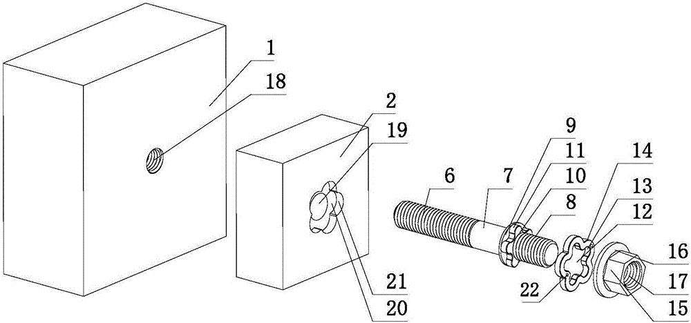
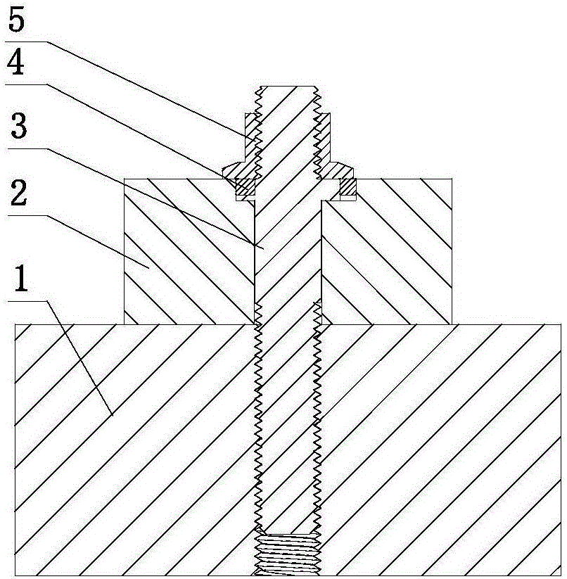
[0208] Such as figure 1 , figure 2 As shown, a fastening connection structure includes a mother body 1, an appendage 2, and a fastening connection assembly.

[0209] The fastening connection assembly includes the screw rod 3, the anti-rotation sleeve 4, and the stopper of the anti-rotation sleeve. The stopper of the anti-rotation sleeve is a blocking nut 5 .

[0210] The screw 3 includes a first external threaded part 6 , a polished rod part 7 , a stopper against rotation and a second external threaded part 8 arranged in sequence. The anti-rotation resisting portion includes a cylindrical resisting circular convex ring 9 and a spline-shaped anti-rotation portion 10 , the anti-rotation portion 10 is connected to the second external thread portion 8 . Five protrusions are formed on the outer periphery of the anti-rotation portion 10 , and each protrusion forms a first anti-rotation portion 11 . The resisting ring 9 protrudes radially from the polished rod portion 7 and the ...

Embodiment 2

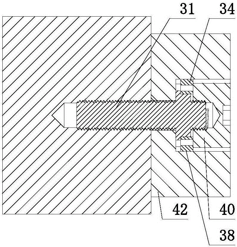
[0221] Such as image 3 , Figure 4 As shown, the difference from Embodiment 1 is that the outer circumference of the anti-rotation portion 32 of the screw 31 is a regular hexagon, and the six planes on the outer periphery of the anti-rotation portion 32 form six first anti-rotation portions 33 arranged in the circumferential direction.

[0222] The hole wall of the anti-rotation through hole 35 of the anti-rotation sleeve 34 cooperates with the outer periphery of the anti-rotation part 32, and the positive hexagonal hole, six planes on the hole wall of the anti-rotation through hole 35 form six circumferentially arranged and the first anti-rotation The second anti-rotation part 36 matched with the part 33. The outer circumference of the anti-rotation sleeve 34 is an intersecting structure of two regular hexagons with the same structure and rotated by 30°. The outer circumference of the anti-rotation sleeve 34 forms twelve pointed-shaped convex teeth, and each pointed-shaped ...

Embodiment 3

[0225] Such as Figure 5 , Figure 6 As shown, the difference from Embodiment 2 is that the stopper of the anti-rotation sleeve is a resisting screw 51 . The screw 52 includes a first external threaded portion 53 and a rotation-preventing resisting portion 55 arranged in sequence. A threaded hole 56 is provided on the end surface of the anti-rotation resisting part 55 away from the end of the first external threaded part 53, and the external threaded part 57 of the resisting screw 51 is threadedly connected with the threaded hole 56 on the screw rod 52, and the screw head 58 of the resisting screw 51 The maximum outer diameter is greater than the minimum inner diameter of the anti-rotation through hole 59 , and the screw head 58 of the resisting screw 51 axially limits the anti-rotation sleeve 60 . The resisting screw 51 is completely accommodated in the first anti-rotation hole 62 of the appendage 61 .


PUM


Abstract

A fastening connection structure comprises a main body, an auxiliary body and a fastening connection assembly. The fastening connection assembly comprises a screw and a rotation stop sleeve. A taking-out device used for taking out the rotation stop sleeve is arranged on the hole wall of a first rotation stop hole and / or the rotation stop sleeve. The screw penetrates through the auxiliary body to be mounted on the main body. The rotation stop sleeve is mounted outside a rotation stop butting part of the screw and inside the first rotation stop hole and is limited in the axial direction. A first rotation stop part on the outer circumference of the rotation stop butting part of the screw is matched with a second rotation stop part on the hole wall of a rotation stop through hole of the rotation stop sleeve to restrain rotation, relative to the rotation stop sleeve, of the screw. A third rotation stop part on the outer circumference of the rotation stop sleeve is matched with a fourth rotation stop part on the hole wall of the first rotation stop hole to restrain rotation, relative to the auxiliary body, of the rotation stop sleeve. The screw, the auxiliary body and the main body are mounted together in a non-rotatable mode. The fastening connection structure has the advantages that the situation that the screw rotates reversely and consequentially is loosened is prevented, and the rotation stop sleeve can be taken out of the first rotation stop hole conveniently, rapidly and reliably.

Description

Technical field: [0001] The invention relates to a fastening connection technology for statically connecting two or more objects with threaded pairs; in particular, it relates to a method for statically connecting crankshaft linkage mechanisms, track structures, aircraft, ships, equipment, aerospace equipment, etc. through threaded pairs. Fastening connection components, fastening connection structures and connections of mechanical parts on key parts of aircraft carriers, spaceships, rockets, engines, nuclear reaction equipment, trains, high-speed rail, rails, steel structure buildings, steel structure bridges, automobiles, etc. method, disassembly method, the use environment of these mechanical parts is particularly harsh, such as large vibration, high temperature environment, heavy load, etc., and the connection reliability of the threaded mechanical static connection is particularly high. Background technique [0002] The thread pair mechanical static connection between o...

Claims


Application Information

Patent Timeline
Patent Type & Authority Applications(China)
IPC IPC(8): F16B35/04F16B37/14F16B37/04F16B43/00F16B39/282F16C3/12
CPCF16B35/041F16B37/041F16B37/14F16B39/282F16B43/00F16C3/12F16B39/26F16B39/28
Inventor 杨东佐
Owner 杨东佐
Why Eureka
Try Eureka