High temperature resistant optical fiber sensor

An optical fiber sensor, high temperature resistant technology, applied in the direction of converting sensor output, using optical devices to transmit sensing components, instruments, etc., can solve the problem of increasing light transmission optical fiber broken wires, dark wires, burning, difference in cooling effect, and affecting monitoring effect And other problems, to achieve the effect of safe and efficient operation, good heat dissipation effect, reliable and stable flame detection

Inactive Publication Date: 2016-12-21
李国 +1
View PDF5 Cites 4 Cited by
  • Summary
  • Abstract
  • Description
  • Claims
  • Application Information

AI Technical Summary

Problems solved by technology

At present, the heat-resistant temperature of the domestically produced optical fiber sensors for combustion detection is mostly below 350°C. In reality, the combustion process of the boiler is affected by factors such as the fluctuation of the cooling air pressure difference and the difference in the cooling effect caused by the

Method used


Image

  • High temperature resistant optical fiber sensor
  • High temperature resistant optical fiber sensor

Examples


Embodiment Construction

[0018] The present invention will be further described below in conjunction with accompanying drawings and examples.

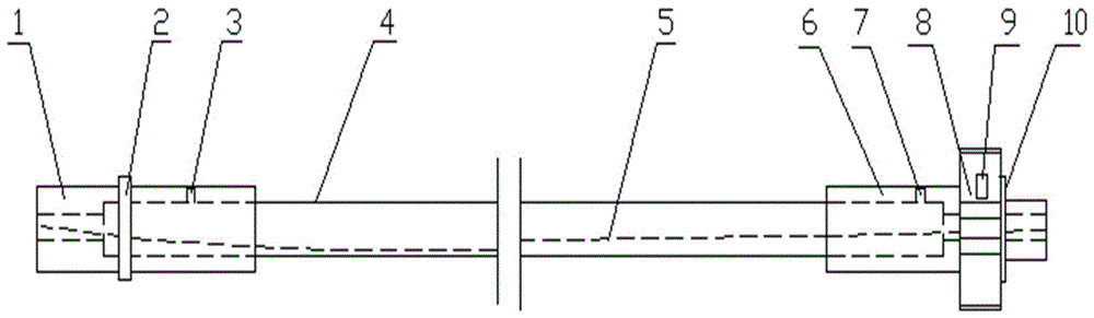
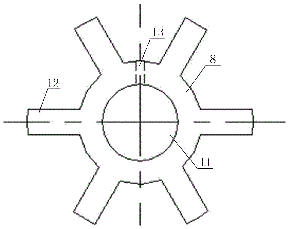
[0019] Such as figure 1 As shown, the structure schematic diagram of the high temperature resistant optical fiber sensor of the present invention is provided, figure 2 A schematic diagram of the structure of the tooth-shaped positioning heat dissipation block in the present invention is given. The high-temperature-resistant optical fiber sensor shown is composed of an optical fiber bundle 5, a stainless steel sleeve 4, a low-temperature joint 1, a high-temperature joint 6, and a tooth-shaped positioning heat dissipation block 8. The optical fiber bundle 5 is located in the stainless steel sleeve 4, and the stainless steel sleeve 4 can protect the optical fiber bundle 5 and can bend to a certain extent along with the optical fiber bundle 5. The low-temperature joint 1 and the high-temperature joint 6 are respectively fixed on both ends of the stainless steel ...


PUM


Abstract

The invention discloses a high temperature resistant optical fiber sensor comprising a stainless steel sleeve tube, an optical fiber bundle, a low temperature connecting head and a high temperature connecting head. The high temperature resistant optical fiber sensor is characterized in that tooth-shaped positioning heat dissipation blocks are fixed at an outer periphery of the high temperature connecting head, a plurality of heat dissipation bars are uniformly distributed at outer peripheries of the tooth-shaped positioning heat dissipation blocks, and central parts of the tooth-shaped positioning heat dissipation blocks are provided with column-shaped holes matched with the high temperature connecting head. A manufacturing method for the high temperature resistant optical fiber sensor comprises the following steps: a, a step of adhesion agent configuration; b, a step of optical fiber cleaning; c, a step of optical fiber pretreatment; d, a step of sizing treatment; e, a step of heating and curing; f, a step of connector head connection; g, a step of heat dissipation block arrangement. According to the high temperature resistant optical fiber sensor disclosed in the invention, the tooth-shaped positioning heat dissipation blocks are fixed at the outer periphery of the high temperature connecting head, the plurality of heat dissipation bars are uniformly distributed at the outer peripheries of the tooth-shaped positioning heat dissipation blocks, heat dissipation area of the high temperature connecting head can be effectively increased, bonding technologies are improved, heat dissipation effects are enhanced, great high temperature (500 DEG C) resistant effects are exerted, and the high temperature resistant optical fiber sensor is suitable for photoelectric signal collection and transmission in fuel coal, fuel oil, fuel gas combustion occasions and other combustion occasions.

Description

technical field [0001] The present invention relates to a high-temperature-resistant optical fiber sensor, more specifically, it relates to a heat-resisting block installed on a high-temperature joint with tooth-shaped positioning and a corresponding bonding process to increase its heat-resistant performance, so that it can be applied in 500 High temperature resistant fiber optic sensor for high temperature occasions. Background technique [0002] Industrial optical fiber sensors are widely used in the detection fields of electric power, locomotives, buildings, pressure vessels, etc., and have obvious effects in checking damage or corrosion of electrical equipment such as boilers, steam turbines, and transformers, and finding fallen objects. High temperature resistant fiber optic sensors are mainly used for real-time monitoring and combustion protection of coal, fuel, gas and other combustion methods. At present, the heat-resistant temperature of the domestically produced o...

Claims


Application Information

Patent Timeline
IPC IPC(8): G01D5/353
CPCG01D5/35374
Inventor 硕楠李国
Owner 李国
Why Eureka
Try Eureka