
Bubble dynamics visualization research apparatus applicable to dynamic movement conditions

A dynamic motion and dynamics technology, applied in the field of experimental devices, can solve the problems of short test pieces, inability to conduct research on bubble dynamics, and inability to conduct research on tracking bubbles, so as to achieve safe operation and save experimental time

Inactive Publication Date: 2016-12-21
HARBIN ENG UNIV
View PDF2 Cites 25 Cited by
  • Summary
  • Abstract
  • Description
  • Claims
  • Application Information

AI Technical Summary

Problems solved by technology

These devices can only study the characteristics of bubble dynamics under normal conditions in a steady state, and cannot carry out research on bubble dynamics under unsteady conditions and combined conditions with natural circulation and narrow channels.
For example: Pan Liangming’s bubble dynamics research device of Chongqing University (Pan Liangming. Bubble behavior and heat transfer during supercooled boiling of vertical rectangular narrow slit flow [D]. Chongqing University, 2002.) can only complete the vertical state Forced circulation bubble dynamics research; and Osaka University's Tomio Okawad's visualized bubble dynamics research device (Tomio Okawa, Tatsuhiro, Isao Kataoka, et al. Bubble rise characteristics after the departure from a nucleation site in vertical upflow boiling of subcooled water [J].Nuclear Engineering and Design,2005,235:1149-1161.) The experimental piece is short and can only observe the characteristics of the bubbles in a specific area, and cannot carry out research on tracking the evolution of the bubbles in the channel

Method used


Image

  • Bubble dynamics visualization research apparatus applicable to dynamic movement conditions
  • Bubble dynamics visualization research apparatus applicable to dynamic movement conditions
  • Bubble dynamics visualization research apparatus applicable to dynamic movement conditions

Examples


Embodiment Construction

[0020] The present invention is described in more detail below in conjunction with accompanying drawing example:

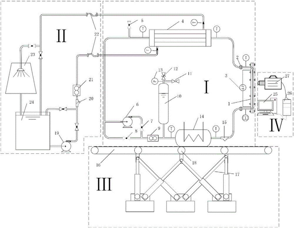
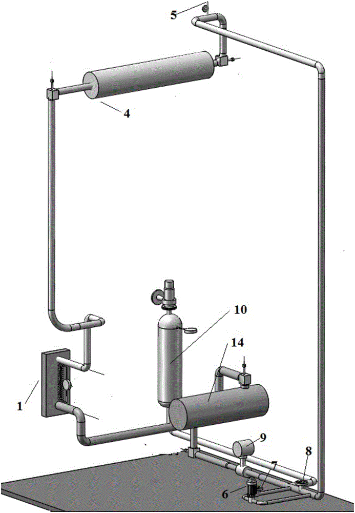
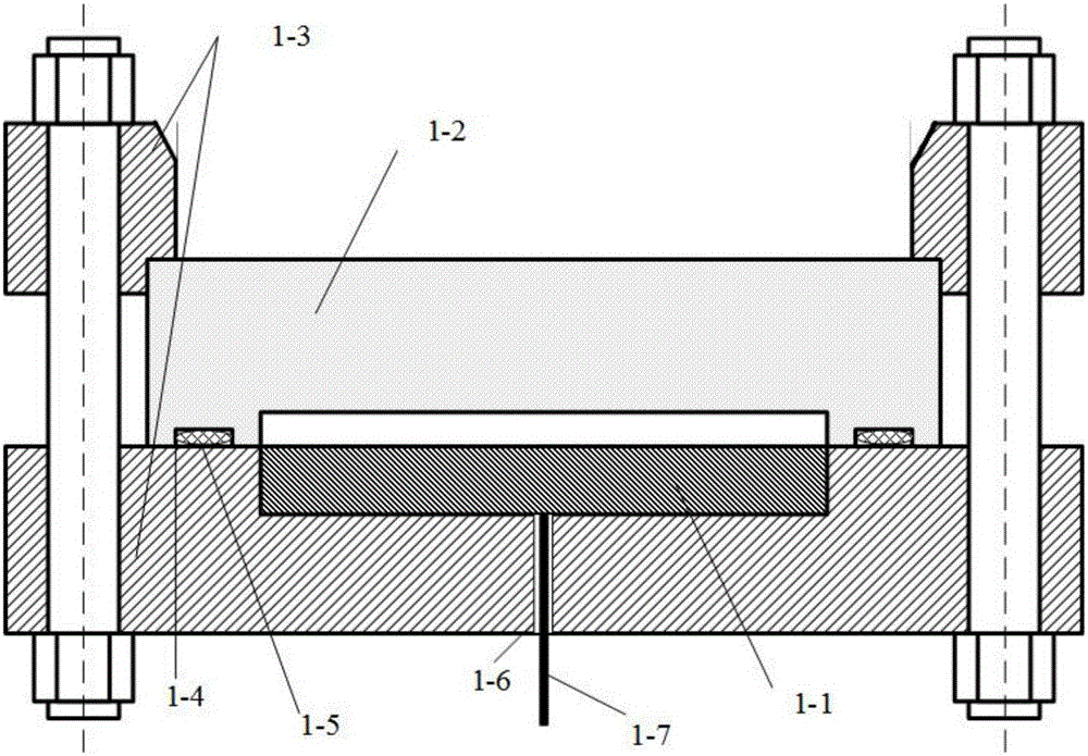
[0021] combine Figure 1-4 , the structure of the present invention, which is suitable for the visualization research of bubble dynamics under dynamic motion conditions, is as follows: it includes four parts: experimental circuit I, cooling circuit II, swing platform III, and data acquisition system IV, and the experimental working medium is deionized water. Experimental loop I consists of narrow passage test piece 1, flange 2, differential pressure sensor 3, condenser 4, exhaust valve 5, centrifugal pump 6, valve 7, valve 8, flowmeter 9, pressure regulator 10, pressure relief valve 11. Safety valve 12, pressure transmitter 13, preheater 14 and filter 15. Swing platform III can be tilted and swayed to simulate the dynamic conditions of ocean and aviation. Condensation circuit II is composed of centrifugal pump 19, filter 20, flow meter 21, connecting hose 22, ai...


PUM


Abstract

The invention aims at providing a bubble dynamics visualization research apparatus applicable to dynamic movement conditions. The bubble dynamics visualization research apparatus comprises a narrow channel experimental element, a preheater, a condenser, an air cooling tower, a water storage tank and a swinging platform, wherein a tube pass inlet of the condenser is communicated with the outlet of the narrow channel experimental element, the tube pass outlet of the condenser is communicated with the preheater, the preheater is communicated with the inlet of the narrow channel experimental element, a shell pass inlet of the condenser is communicated with the water storage tank, the shell pass outlet of the condenser is communicated with the inlet of the air cooling tower, the outlet of the air cooling tower is communicated with the water storage tank, the narrow channel experimental element is vertically fixed on the swinging platform, the preheater and the condenser are arranged on the swinging platform in parallel, a hydraulic driving mechanism is arranged below the swinging platform, a high-speed camera is arranged beside the narrow channel experiment element, and the high-speed camera is connected with a computer by virtue of a data acquisition board. The bubble dynamics visualization research apparatus provided by the invention can realize bubble behaviour research under narrow channel, natural circulation and dynamic movement conditions and has the advantages of adjustable multiple variables, quick switching of different operation conditions and high automation degree.

Description

technical field [0001] The invention relates to an experimental device, in particular to an experimental device for bubble dynamics. Background technique [0002] Boiling heat transfer widely exists in the fields of thermal energy, chemical industry and nuclear reactors. The behavior characteristics of bubbles are closely related to the boiling heat transfer characteristics of fluids. Therefore, the study of bubble dynamics is one of the topics that scholars from all over the world pay attention to. Movement behavior such as bubble formation and detachment will be affected by many factors such as flow channel structure, flow mode, and flow stability. Current research mainly focuses on large containers, forced circulation, and stable conditions. For fine channels, natural circulation, and dynamic load Less under special conditions such as sports. In fact, thermal power plants under marine and aerospace conditions have special conditions such as rocking instability, natural c...

Claims


Application Information

Patent Timeline
Patent Type & Authority Applications(China)
IPC IPC(8): G01N21/84
CPCG01N21/84G01N2021/8405
Inventor 曹夏昕杨勇勇俞胜之阎昌琪杨宽田旺盛田春平戴斌熊坤
Owner HARBIN ENG UNIV
Learn More