Non-destructive metal surface defect microscopic detection method

A technology for metal surface and microscopic inspection, which is applied in the direction of optical testing for flaws/defects, measuring devices, and material analysis through optical means. Higher requirements and other issues, to achieve the effect of wide application range, high promotion value, and increase product qualification rate

Inactive Publication Date: 2016-12-21
AECC AVIATION POWER CO LTD
View PDF4 Cites 5 Cited by
  • Summary
  • Abstract
  • Description
  • Claims
  • Application Information

AI Technical Summary

Problems solved by technology

At present, there is only a single non-destructive microscopic observation method for the abnormal display on the surface of metal parts at home and abroad. Portable microscopes are generally used for observation, but this method has high requirements on the shape and surface of the parts, and the scope of application is narrow.

Method used


Image

  • Non-destructive metal surface defect microscopic detection method
  • Non-destructive metal surface defect microscopic detection method
  • Non-destructive metal surface defect microscopic detection method

Examples


Embodiment 1

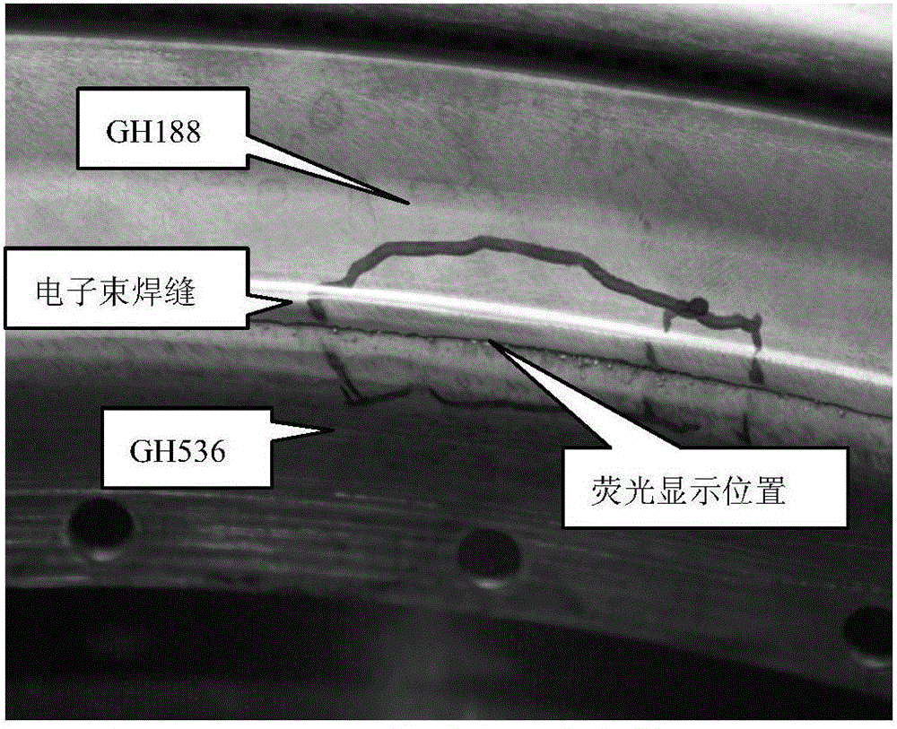
[0031] see figure 1 , taking the electron beam welding between GH188 thin-wall and GH536 thin-wall, as an example, it is found that there are suspected cracks displayed linearly near the weld by fluorescence, and the specific implementation steps are described as follows:

[0032] Since the fluorescent display part is located in the weld seam, it is not easy to judge whether the linear display is a crack, so the surface treatment is not performed on this part, and it is directly detected.

[0033] 1. Clean the fluorescent display position of the welding seam with a cotton ball soaked in acetone.

[0034] 2. Dry the weld surface with a hair dryer.

[0035] 3. Cut the AC paper into strips with a width of 15mm and a length of 40mm.

[0036] 4. Clamp the pre-cut AC paper with tweezers, suck an appropriate amount of acetone with a small dropper, first drop a few drops on the surface of the weld to be tested, so that it soaks the entire surface to be tested, and then drop acetone ...

Embodiment 2

[0043] After a certain forging was processed, the corrosion process inspection was carried out, and it was found that there were abnormal displays in some areas, see Figure 4 , in order to observe the metal microstructure, surface treatment is carried out on the abnormal display area. Then, according to the method of Example 1, the AC paper was covered on the abnormal display position and rubbed, and then the AC paper was observed microscopically. see Figure 5 , Image 6 , there is a significant difference in the grain size level between the abnormal display area and the normal area, the grain size of the normal area is 10, and the grain size of the abnormal display area is 5. According to the results of microscopic observation, the relevant standards are used to determine whether the part can be used in this situation.

[0044] The method of the present invention has the advantages of simple operation and wide application range, and the type of defects can be judged by o...


PUM


Abstract

The present invention provides a non-destructive metal surface defect microscopic detection method. According to the present invention, when the abnormal display appears on the surface of a metal part, the reason cannot be macroscopically determined, and the condition is required to be determined through the further microscopic observation, the non-destructive metal surface defect microscopic detection method is used; AC paper covers the surface of a part to develop the defect appearance so as to achieve the microscopic observation of the part surface defect and determine the defect type, such that the detection period can be effectively shortened, the parts scrap risk can be reduced, the product qualification rate can be improved, and the production cost can be reduced; and the method has characteristics of simple operation, wide application range, high promotion value, and good market prospect.

Description

technical field [0001] The invention is suitable for microscopic observation of metal surface morphology, and is a method for inspecting metal surface defects on the premise of not destroying metal parts. Background technique [0002] During the processing of metal parts, abnormalities may appear on the surface, such as spots, pits, suspected cracks, and defects found by non-destructive testing. However, since most parts can only be judged by macroscopic observation, the cause of abnormal display cannot be judged, so microscopic observation is needed to judge it. If the part is dissected and the metallographic sample is prepared for microscopic observation, not only the test cycle will be longer, but also the part will be scrapped due to direct sampling inspection and cannot be used any more. Through the non-destructive metal surface defect inspection method, not only the test period is shortened, but also the parts that can be used can be recovered without damaging the par...

Claims


Application Information

Patent Timeline
Patent Type & Authority Applications(China)
IPC IPC(8): G01N21/91G01N21/01
CPCG01N21/91G01N21/01
Inventor 张爽刘国良孙智君刘荣侯春梅刘磊魏磊管鹏
Owner AECC AVIATION POWER CO LTD
Why Eureka
Try Eureka