
Mode multiplexing demultiplexer based on silicon-based optical waveguide mode matching

A silicon-based optical waveguide and demultiplexer technology, which can be used in optical guides, optics, instruments, etc., can solve problems such as complex structure, and achieve the effect of expanding transmission capacity and simple structure.

Active Publication Date: 2016-12-21
BEIJING JIAOTONG UNIV
View PDF3 Cites 25 Cited by
  • Summary
  • Abstract
  • Description
  • Claims
  • Application Information

AI Technical Summary

Problems solved by technology

Literature [Dai D, Wang J, Shi Y, "Silicon mode (de) multiplexer enabling high capacity photonic networks-on-chip with a single-wavelength-carrier light", Optics Letters (2013) 1422-1424] gives a A mode multiplexer based on multi-level mode coupling, but its structure involves multiple tapered optical waveguides and needs to strictly control the front and rear widths of the tapered waveguides, so the structure is relatively complicated

Method used


Image

  • Mode multiplexing demultiplexer based on silicon-based optical waveguide mode matching
  • Mode multiplexing demultiplexer based on silicon-based optical waveguide mode matching
  • Mode multiplexing demultiplexer based on silicon-based optical waveguide mode matching

Examples


Embodiment Construction

[0034] Hereinafter, embodiments of the mode multiplexing demultiplexer of the present invention will be described with reference to the accompanying drawings.

[0035] The examples described here are specific specific implementations of the present invention, and are used to illustrate the concept of the present invention. They are all explanatory and exemplary, and should not be construed as limiting the implementation of the present invention and the scope of the present invention. In addition to the embodiments described here, those skilled in the art can also adopt other obvious technical solutions based on the claims of the application and the contents disclosed in the description, and these technical solutions include adopting any obvious changes made to the embodiments described here. Replacement and modified technical solutions.

[0036] The accompanying drawings in this specification are schematic diagrams, which assist in explaining the concept of the present inventi...


PUM


Abstract

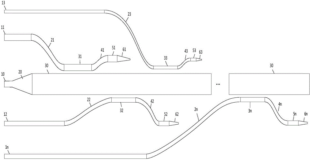
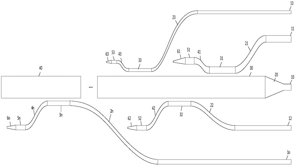
The invention provides a mode multiplexing demultiplexer based on silicon-based optical waveguide mode matching. When the mode multiplexing demultiplexer is used as a multiplexer, the mode multiplexing demultiplexer comprises n strip-shaped waveguides different in width and adopted as input optical waveguides, wherein the 0-th input optical waveguide (10) is a single-mode optical waveguide and the tail end of the single-mode optical waveguide is sequentially connected with a conical optical waveguide (20), a multi-mode optical waveguide (30) and a multiplexer output end (40). The tail end of the n-th input optical waveguide (1n) is sequentially connected with an S-shaped curved optical waveguide structure (2n), a coupling region optical waveguide (3n), a second S-shaped curved optical waveguide structure (4n), a small-section straight waveguide (5n) and a conical waveguide (6n). When the mode multiplexing demultiplexer is used as a demultiplexer, the output end and the input end of the multiplexer are exchanged with each other according to the reversibility of the optical path. Therefore, the mode demultiplexing can be realized. In this way, the mode multiplexing demultiplexer becomes a demultiplexer. The mode multiplexing demultiplexer is simple in structure and high in mode conversion efficiency, which enables the multiplexing and the demultiplexing of the TE mode and the TM mode.

Description

technical field [0001] The invention relates to optical communication mode multiplexing technology, in particular to a mode multiplexing demultiplexer. Background technique [0002] With the development of network business, people have more and more demands on optical fiber communication capacity, and an effective way to increase long-distance communication capacity is to use wavelength division multiplexing (WDM) technology. However, the wavelength division multiplexing system needs expensive components such as multi-channel lasers or tunable lasers, so the cost is very high, which largely limits its wide application in optical communication systems. Moreover, due to the limitation of the inherent nonlinear effect of the single-mode optical fiber itself, the transmission capacity of the single-mode optical fiber is close to the limit, which cannot meet people's increasing demand for information. Therefore, mode multiplexing technology is proposed to transmit different info...

Claims


Application Information

Patent Timeline
IPC IPC(8): G02B6/293
CPCG02B6/29332G02B6/2938
Inventor 乐燕思王智李智勇李强孙翀灰宋晓佳
Owner BEIJING JIAOTONG UNIV
Learn More