Machine vision positioning method for automatic screw assembling

A machine vision and automatic assembly technology, applied in the direction of instruments, image data processing, image feedback, etc., can solve the problems of assembly failure, high requirements for feature point selection, low precision, etc., achieve high precision, overcome assembly failure, and shorten time Effect

Active Publication Date: 2016-12-21
HEBEI UNIV OF TECH
View PDF4 Cites 30 Cited by
  • Summary
  • Abstract
  • Description
  • Claims
  • Application Information

AI Technical Summary

Problems solved by technology

[0005] The technical problem to be solved by the present invention is to provide a machine vision positioning method for automatic screw assembly, use the Hough transform method to search for circles in the image, and use the center of the circle as the positioning point, which overcomes the disadvantag

Method used


Image

  • Machine vision positioning method for automatic screw assembling
  • Machine vision positioning method for automatic screw assembling
  • Machine vision positioning method for automatic screw assembling

Examples


Embodiment 1

[0053] This embodiment is a machine vision positioning method for automatic assembly of screws on a TV backplane, and the implementation steps are as follows:

[0054] A. Devices involved:

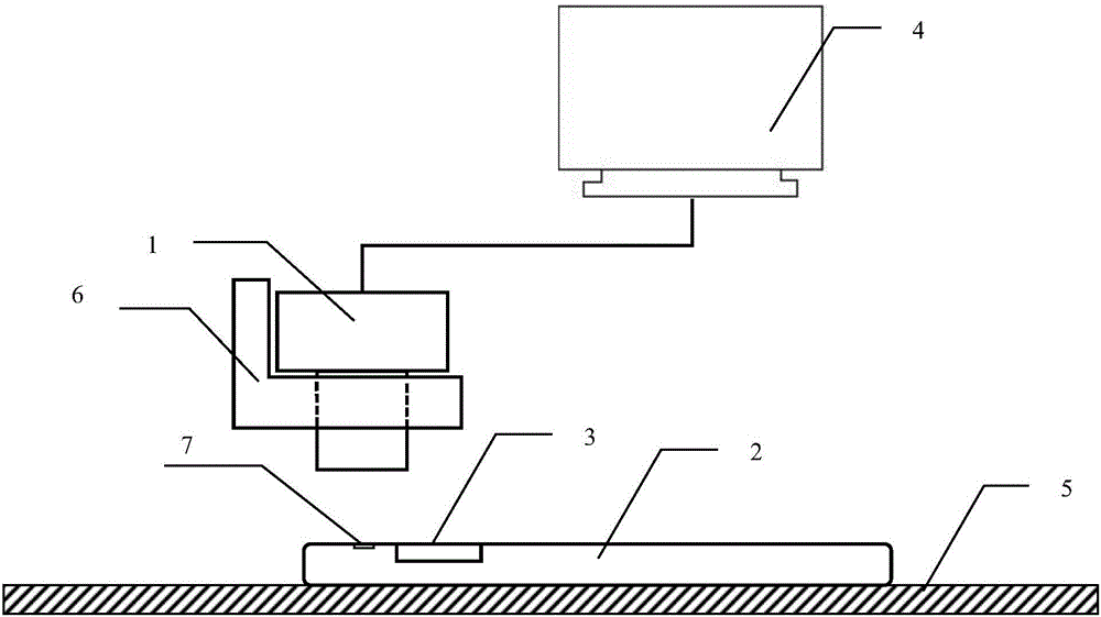
[0055] The devices involved in the implementation of the machine vision positioning method for automatic screw assembly include an industrial camera 1, the product part 2 to be assembled is a TV backplane, an industrial computer 4, a workbench 5 of an automatic screw assembly device, and an industrial camera installation slot 6 ;

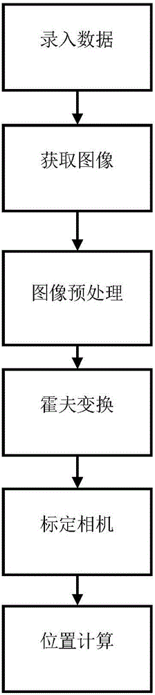
[0056] B. The steps are as follows:

[0057] The first step is to enter data:

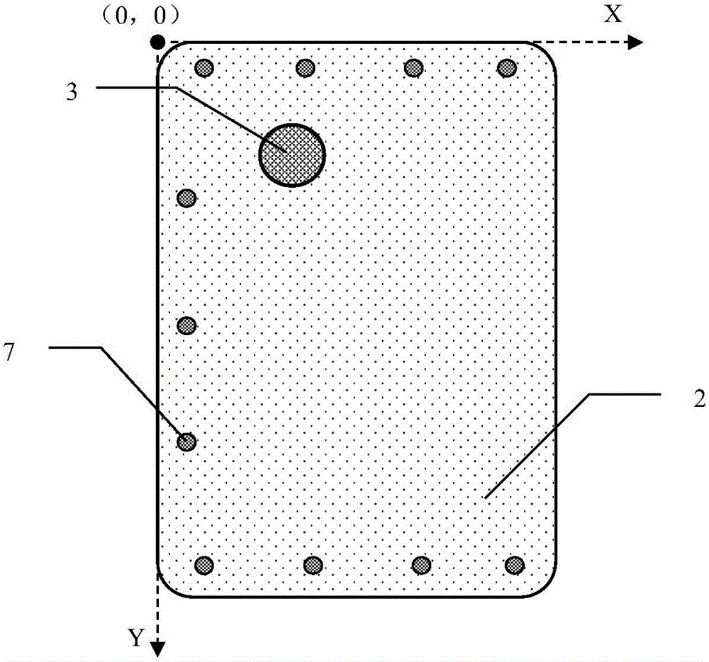
[0058] First collect the size information of the TV backplane of the product part 2 to be assembled and the distribution information of the round holes on the surface, as well as the distribution position information of each screw hole and the position of the screw hole 7 on the product part to be assembled. The contour circle is the characteristic circle 3 of the product part to ...

Embodiment 2

[0082] Except for the following parts, others are the same as Example 1:

[0083] The first step is to enter data:

[0084] First collect the size information of the TV backplane of the product part 2 to be assembled and the distribution information of the round holes on the surface, as well as the distribution position information of each screw hole and the position of the screw hole 7 on the product part to be assembled. The contour circle is the characteristic circle 3 of the product part to be assembled to be positioned, the radius of the hole and the location information of the characteristic circle 3 of the product part to be assembled to be positioned are recorded and used as the feature information of the image, and the product part to be assembled is 2. The above-mentioned relevant information of the TV backplane is entered into the measurement software of the industrial computer 4; the length of the TV backplane of the product part 2 to be assembled is 650mm, and the...

Embodiment 3

[0096] Except for the following parts, others are the same as Example 1:

[0097] The first step is to enter data:

[0098] First collect the size information of the TV backplane of the product part 2 to be assembled and the distribution information of the round holes on the surface, as well as the distribution position information of each screw hole and the position of the screw hole 7 on the product part to be assembled. The contour circle is the characteristic circle 3 of the product part to be assembled to be positioned, the radius of the hole and the location information of the characteristic circle 3 of the product part to be assembled to be positioned are recorded and used as the feature information of the image, and the product part to be assembled is 2. The above-mentioned relevant information of the TV backplane is entered into the measurement software of the industrial computer 4; the length of the TV backplane of the product part 2 to be assembled is 455mm, and the...


PUM


Abstract

The invention, which relates to the field of metering equipment employing an optical method as a feature, provides a machine vision positioning method for automatic screw assembling. The method comprises steps of inputting and recording data, obtaining an image, carrying out image pretreatment, carrying out Hough transform treatment, calibrating a camera, and calculating a position. According to the method, a circle in an image is searched by using the Hough transform method and the center of the circle is used as a positioning point, so that defects of high selection requirement and low precision for feature point selection according to the existing visual positioning method can be overcome; and a defect of an assembling failure caused by inaccurate product position fixation by a clamp during the automatic screw assembling process in the prior art can be overcome.

Description

technical field [0001] The technical solution of the present invention relates to a measuring device characterized by adopting an optical method, in particular a machine vision positioning method for automatic assembly of screws. Background technique [0002] In today's manufacturing industry, the manufacture of electronic products, auto parts and home appliances, etc. is an important part. In the manufacture and assembly of products in these industries, there are often products that need to be assembled with a large number of screws. The efficiency of manually assembling screws is very low, and it is easy to miss screws. Therefore, nowadays manufacturing enterprises have begun to use automatic screw assembly systems with a complete set of control software to automatically assemble screws. The screw automatic assembly system is composed of industrial computer, electric actuator and corresponding control software. In the screw automatic assembly system, the screw hole posit...

Claims


Application Information

Patent Timeline
IPC IPC(8): G06T7/00G06T7/60G06T5/30G06T5/20G06T5/00G06T1/00
CPCG06T1/0014G06T5/002G06T5/20G06T5/30G06T2207/10004G06T2207/20028
Inventor 郭欣张大鹏赵天骄牛红闯
Owner HEBEI UNIV OF TECH
Why Eureka
Try Eureka