
Continuous wave magnetron waveguide excitation device

A technology of excitation device and magnetron, which is applied in the direction of magnetron, discharge tube, transit time type electron tube, etc., can solve the design requirements that cannot meet the miniaturization and miniaturization of microwave generators, and the volume of microwave generators is large, etc. problem, to achieve the effect of reducing space, reasonable structure design and stable performance

Inactive Publication Date: 2016-12-21
NANJING SANLE MICROWAVE TECH DEV +1
View PDF8 Cites 1 Cited by
  • Summary
  • Abstract
  • Description
  • Claims
  • Application Information

AI Technical Summary

Problems solved by technology

[0002] The continuous wave magnetron has the advantages of high efficiency, simple structure, strong load resistance, and adapts to the state change of the heating object; it is economical and convenient to directly supply power with alternating current; but most of the continuous wave magnetrons in the prior art use electromagnets to generate magnetic fields , when the electromagnet is used, the volume of the microwave generator will be relatively large, and the waveguide excitation cavity in the prior art needs to use adjustment screws to meet the performance requirements. This existing structural design cannot meet the requirements of the microwave generator. The miniaturization and miniaturization design requirements greatly limit its application

Method used


Image

  • Continuous wave magnetron waveguide excitation device
  • Continuous wave magnetron waveguide excitation device
  • Continuous wave magnetron waveguide excitation device

Examples


Embodiment 1

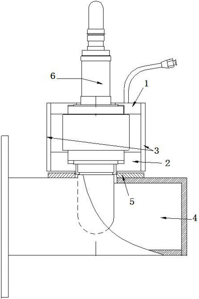
[0023] Such as Figure 1 to Figure 4 As shown, a continuous wave magnetron waveguide excitation device includes an upper magnetic circuit 1, a lower magnetic circuit 2 located below the upper magnetic circuit 1, and magnetic circuit side plates located on both sides of the upper magnetic circuit 1 and the lower magnetic circuit 2 3. The CK-147 continuous wave magnetron 6 installed in the middle of the upper magnetic circuit 1, the lower magnetic circuit 2 and the magnetic circuit side plate 3, the installation base 5 located under the lower magnetic circuit 2 and the BJ- 9 waveguide excitation cavity 4 .

[0024] In the continuous wave magnetron waveguide excitation device described above, the lower magnetic circuit 2 adopts a raised ring structure, the upper magnetic circuit 1 and the lower magnetic circuit 2 are both made of samarium-cobalt permanent magnet materials, and the magnetic circuit side plate 3 is made of pure iron material .

[0025] In the continuous wave magn...


PUM


Abstract

The invention discloses a novel continuous wave magnetron waveguide excitation device, which comprises an upper magnetic circuit (1), a lower magnetic circuit (2) located below the upper magnetic circuit (1), and a lower magnetic circuit (2) located under the upper magnetic circuit (1) and the lower magnetic circuit. The magnetic circuit side plates (3) on both sides of the magnetic circuit (2), the CK‑147 continuous wave magnetron ( 6), the installation base (5) located under the lower magnetic circuit (2) and the BJ-9 waveguide excitation cavity (4) located under the installation base (5). Through simulation and a large number of test screenings, the present invention has reasonable structural design and stable performance. It adopts the upper magnetic circuit and lower magnetic circuit structure of samarium cobalt permanent magnet material, and the magnetic circuit side plate adopts pure iron material. Using adjusting screws, the distance from the installation hole to the short-circuit surface is 81mm±0.5mm, and the minimum total length of the excitation cavity is about 160mm, which can meet the needs of miniaturization and miniaturization.

Description

technical field [0001] The invention belongs to the field of vacuum electronic devices, and in particular relates to a continuous wave magnetron waveguide excitation device. Background technique [0002] The continuous wave magnetron has the advantages of high efficiency, simple structure, strong load resistance, and adapts to the state change of the heating object; it is economical and convenient to directly supply power with alternating current; but most of the continuous wave magnetrons in the prior art use electromagnets to generate magnetic fields , when the electromagnet is used, the volume of the microwave generator will be relatively large, and the waveguide excitation cavity in the prior art needs to use adjustment screws to meet the performance requirements. This existing structural design cannot meet the requirements of the microwave generator. The design requirements of miniaturization and miniaturization greatly limit its application. Contents of the invention...

Claims


Application Information

Patent Timeline
IPC IPC(8): H01J25/50H01J23/34
CPCH01J25/50H01J23/34H01J2223/34H01J2225/50
Inventor 王荣川刘友春孙陵斌王敏
Owner NANJING SANLE MICROWAVE TECH DEV
Learn More