Fuel cell reaction device

A fuel cell and reaction device technology, applied in the direction of fuel cells, fuel cell additives, fuel cell heat exchange, etc., can solve the problems of poor operation stability, high cost investment, low reaction efficiency, etc., and achieve small heat loss and protection safety , high heat transfer efficiency

Inactive Publication Date: 2016-12-21
GUANGDONG UNIV OF TECH
View PDF4 Cites 4 Cited by
  • Summary
  • Abstract
  • Description
  • Claims
  • Application Information

AI Technical Summary

Problems solved by technology

[0004] The purpose of the present invention is to solve the problems of low reaction efficiency, high cost input, low cooling efficiency and poor operation stability of the existing fuel cell, and provide a fuel cell with a plate heat exchanger structure, which has high reaction efficiency and good heat exchange efficiency , low cost and stable and reliable fuel cell reaction device

Method used


Image

  • Fuel cell reaction device
  • Fuel cell reaction device
  • Fuel cell reaction device

Examples


Embodiment 1

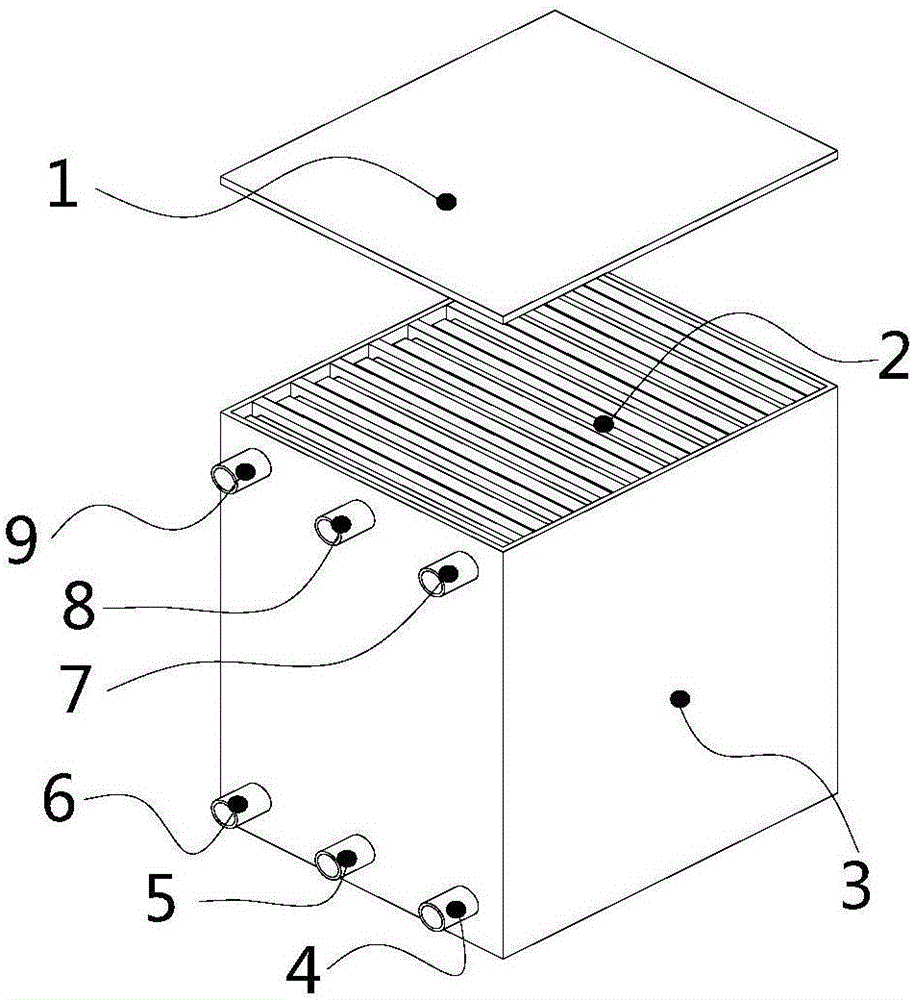
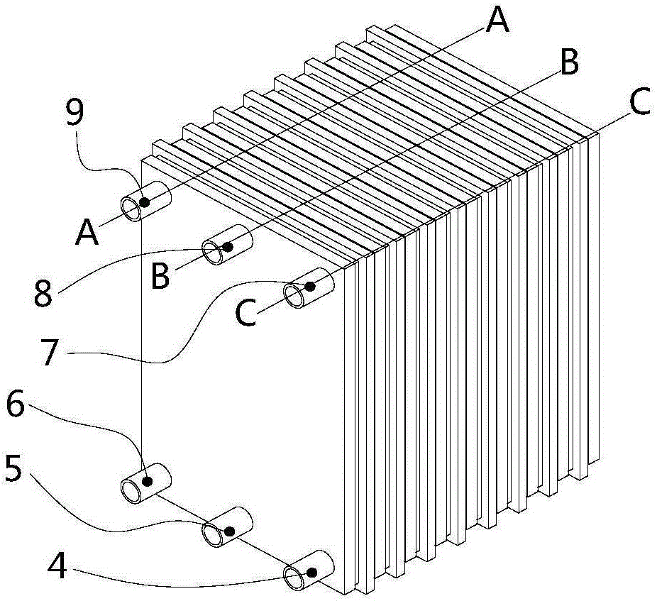
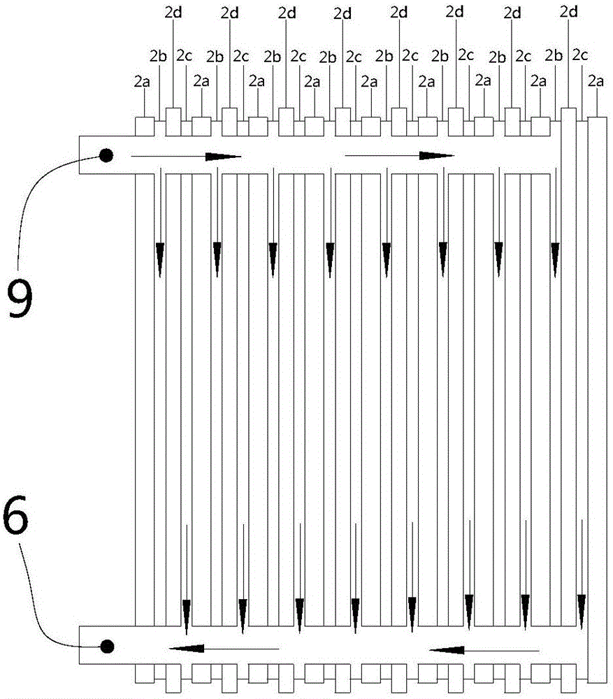
[0023] refer to Figure 1-5 , the present embodiment relates to a fuel cell reaction device, in specific use; the cathode fuel enters the cathode chamber 2c from the cathode fuel inlet channel 7 (see Figure 5 ), the anode material enters the anode chamber 2b from the anode fuel inlet channel 9 (see image 3 ); After fully reacting, the cathode fuel flows out from the cathode fuel outlet channel 6 (see image 3 ), the anode material flows out from the anode fuel outlet channel 4 (see Figure 5 ); Simultaneously, the cooling fluid flows through the cooling plate 2a from the cooling fluid inlet passage 8, and flows out from the cooling fluid outlet passage 5 after cooling the cathode chamber 2c and the anode chamber 2b (see Figure 4 ).

[0024] The fuel cell reaction body 2 is "cooling plate 2a—anode chamber 2b—proton exchange membrane 2d—cathode chamber 2c—cooling plate 2a—anode chamber 2b—proton exchange membrane 2d—cathode chamber 2c..." Plate heat exchanger structure; h...


PUM


Abstract

The invention discloses a fuel cell reaction device. The fuel cell reaction device comprises a fuel cell reaction body and a box body, wherein the fuel cell reaction body is placed in the box body and is formed by sequentially splicing a cooling plate, a positive electrode chamber, a proton exchange membrane and a negative electrode chamber, a negative electrode fuel inlet passage, a cooling fluid inlet passage and a positive electrode fuel inlet passage are arranged at an upper end of the fuel cell reaction body at intervals, and a positive electrode fuel outlet passage, a cooling fluid outlet passage and a negative electrode fuel outlet passage are arranged at a lower end of the fuel cell reaction body at intervals. The fuel cell reaction device is used as the fuel cell reaction body and simultaneously used as a fuel cell heat sink, the reaction device and the heat sink are integrated, a negative electrode fuel and a positive electrode fuel perform chemical reaction through various passages, the fuel reaction area is expanded due to the narrow and zigzag passages, and the fuel reaction efficiency is improved; and the fuel cell reaction device is compact in structure and small in occupancy area, and the power of the fuel cell is improved.

Description

technical field [0001] The invention belongs to the technical field of fuel cells, in particular to a fuel cell reaction device. Background technique [0002] After nearly 20 years of rapid development, proton exchange membrane fuel cell technology has made great progress and successfully solved many problems. However, in order to realize proton exchange membrane fuel cells, there are still problems such as low volume specific power, thermal safety problems caused by reaction heat, and high cost, which limit its commercialization in electric vehicles and other fields. In order to realize the commercialization of fuel cell electric vehicles, the performance of fuel cell electric vehicles must be equivalent to or even better than that of current internal combustion engine vehicles, and at the same time, the price is equal to or even lower than that of current internal combustion engine vehicles. The current cost of fuel cell electric vehicles is relatively high. How to impro...

Claims


Application Information

Patent Timeline
Patent Type & Authority Applications(China)
IPC IPC(8): H01M8/04007H01M8/04029H01M8/0276
CPCH01M8/0276H01M8/04007H01M8/04029Y02E60/50
Inventor 王长宏李娜李庭震
Owner GUANGDONG UNIV OF TECH
Why Eureka
Try Eureka