A DC-DC Voltage Converter

A DC voltage and converter technology, applied in the direction of converting DC power input to DC power output, adjusting electrical variables, instruments, etc., can solve problems such as the inability to achieve constant voltage performance, achieve reduced circuit space, excellent results, and cost reduction Effect

Active Publication Date: 2019-01-25
FAFA AUTOMOBILE (CHINA) CO LTD
View PDF4 Cites 0 Cited by
  • Summary
  • Abstract
  • Description
  • Claims
  • Application Information

AI Technical Summary

Problems solved by technology

[0006] Based on this, it is necessary to provide a DC-DC voltage converter aiming at the technical problem that constant voltage performance cannot be achieved between multiple load devices of the same voltage source in the prior art

Method used


Image

  • A DC-DC Voltage Converter
  • A DC-DC Voltage Converter
  • A DC-DC Voltage Converter

Examples


Embodiment 1

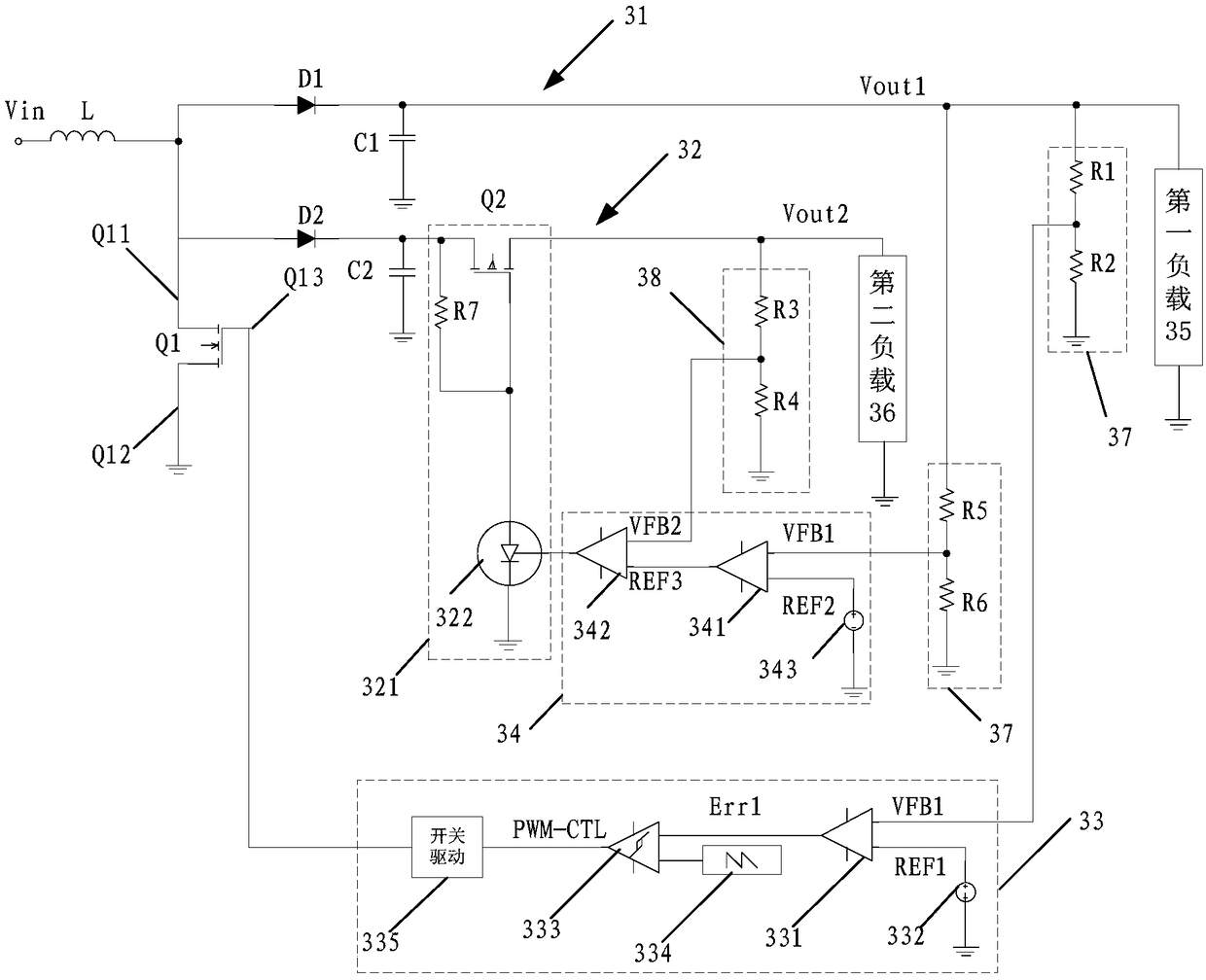
[0037] Such as image 3 Shown is a circuit schematic diagram of a DC-DC voltage converter provided by an embodiment of the present invention, including: an inductor L, a switching device Q1, a first voltage feedback control circuit 33, a first rectification branch 31, at least one A second rectification branch 32 and at least one second voltage feedback control circuit 34;

[0038] One end of the inductor L is used to connect to the DC voltage source Vin, and the other end is respectively connected to the input end of the first rectification branch 31, the input end of the second rectification branch 32, and the switching device Q1. The first switch end Q11 is connected, the second switch end Q12 of the switching device Q1 is grounded, the output end of the first rectification branch 31 is used to supply power to the first load 35, and the output end of the second rectification branch 32 is used for for supplying power to the second load 36;

[0039] The first voltage feedba...

Embodiment 2

[0048] A DC-DC voltage converter provided by an optional embodiment of the present invention includes: an inductor L, a switching device Q1, a first voltage feedback control circuit 33, a first rectification branch 31, and at least one second rectification branch 32 And at least one second voltage feedback control circuit 34 .

[0049] One end of the inductor L is used to connect to the DC voltage source Vin, and the other end is respectively connected to the input end of the first rectification branch 31, the input end of the second rectification branch 32, and the switching device Q1. The first switch end Q11 is connected, the second switch end Q12 of the switching device Q1 is grounded, the output end of the first rectification branch 31 is used to supply power to the first load 35, and the output end of the second rectification branch 32 is used for for supplying power to the second load 36 .

[0050] The first rectification branch 31 also includes a first voltage dividin...

Embodiment 3

[0066] Such as Figure 4 Shown is a schematic circuit diagram of a DC-DC voltage converter provided by another alternative embodiment of the present invention, including: an inductor L, a switching device Q1, a first voltage feedback control circuit 33, and a first rectification branch 31 , at least one second rectification branch circuit 32 and at least one second voltage feedback control circuit 34;

[0067] One end of the inductor L is used to connect to the DC voltage source Vin, and the other end is respectively connected to the input end of the first rectification branch 31, the input end of the second rectification branch 32, and the switching device Q1. The first switch end Q11 is connected, the second switch end Q12 of the switching device Q1 is grounded, the output end of the first rectification branch 31 is used to supply power to the first load 35, and the output end of the second rectification branch 32 is used for for supplying power to the second load 36;

[0...


PUM


Abstract

The invention provides a direct current-direct current voltage converter which comprises an inductor, a switch device, a first voltage feedback control circuit, a first rectification branch, at least one second rectification branch and at least one second feedback control circuit. The first voltage feedback control circuit is used for acquiring the output voltage of the first rectification branch output end to the first output end of a first load and using the output voltage as first feedback voltage, and controlling the first switch end and the second switch end of the switch device to switch on and off according to the first feedback voltage. The second feedback control circuit is used for acquiring the output voltage of the second rectification branch output end to the second output end of a second load and using the output voltage as second feedback voltage, and controlling the resistance of a controlled resistance circuit of the second rectification branch according to the second feedback voltage. According to the invention, the output end of each rectification branch is provided with an independent voltage feedback control circuit, so as to ensure the constant voltage performance of the output end of each rectification branch.

Description

technical field [0001] The invention relates to the electrical related technical field, in particular to a DC-DC voltage converter. Background technique [0002] At present, a large number of electronic and electrical equipment and products use batteries as power sources, but the output voltage of batteries is not constant and the voltage is low. Therefore, a large number of step-up and voltage-stabilizing technologies have emerged as the times require in practical applications. However, the output feedback of the existing boost circuit can only track one output. When there are multiple output loads, the noise crosstalk between the loads is serious, and the output ripple is difficult to suppress; it is impossible to achieve independent noise control for each output load; a variety of different load voltages When required by Wenbo, multiple completely isolated DC boost units are required, resulting in duplication of circuit design and waste of component costs. [0003] Such...

Claims


Application Information

Patent Timeline
Patent Type & Authority Patents(China)
IPC IPC(8): H02M3/156
CPCH02M3/156
Inventor 袁沂
Owner FAFA AUTOMOBILE (CHINA) CO LTD
Why Eureka
Try Eureka