Wet type sand-blasting machine

A sandblasting machine and sandblasting technology, applied in the field of sandblasting machines, can solve the problems of increased size of sandblasting machines, polluting the environment, high cost and use cost, etc., to improve the processing quality of workpieces, improve the effect of sandblasting cleaning, and improve The effect of workpiece machining efficiency

Active Publication Date: 2017-01-04
永红保定铸造机械有限公司
View PDF7 Cites 13 Cited by
  • Summary
  • Abstract
  • Description
  • Claims
  • Application Information

AI Technical Summary

Problems solved by technology

[0002] Sand blasting machine is used to clean the scale, residual salt and welding slag of heat treatment parts, welding parts, castings, forgings, etc.; clean the tiny burrs and surface residues of machined parts; change the surface roughness of workpieces; renovate old parts, etc. The currently used sandblasting machine, the sandblasting spray gun adopts a fixed installation method. When the sandblasting machine is in operation, the sandblasting spray gun forms fixed-point spraying. Since the spraying range is relatively fixed, a spraying dead angle is formed. Some parts of the workpiece cannot be sprayed, which affects the quality of the workpiece. The quality of surface treatment, in order to spray as much as possible on the surface of the workpiece, we can only place fewer workpieces in the cleaning room, and the sandblasting machine processes fewer workpieces each time. If it is to increase the processing volume of a single workpiece, it is necessary to increase the roller In this way, the size of the entire sandblasting machine will increase significantly and the cost will increase; at the same time, the currently used sandblasting machine itself has no dust removal function
A large amount of dust is produced during sandblasting operation, which seriously pollutes the environment, and the cost of dust removal equipment and use cost is relatively high by using separate dust removal equipment

Method used


Image

  • Wet type sand-blasting machine
  • Wet type sand-blasting machine

Examples


Embodiment Construction

[0015] The present invention will be further described in detail below in conjunction with the accompanying drawings and specific embodiments.

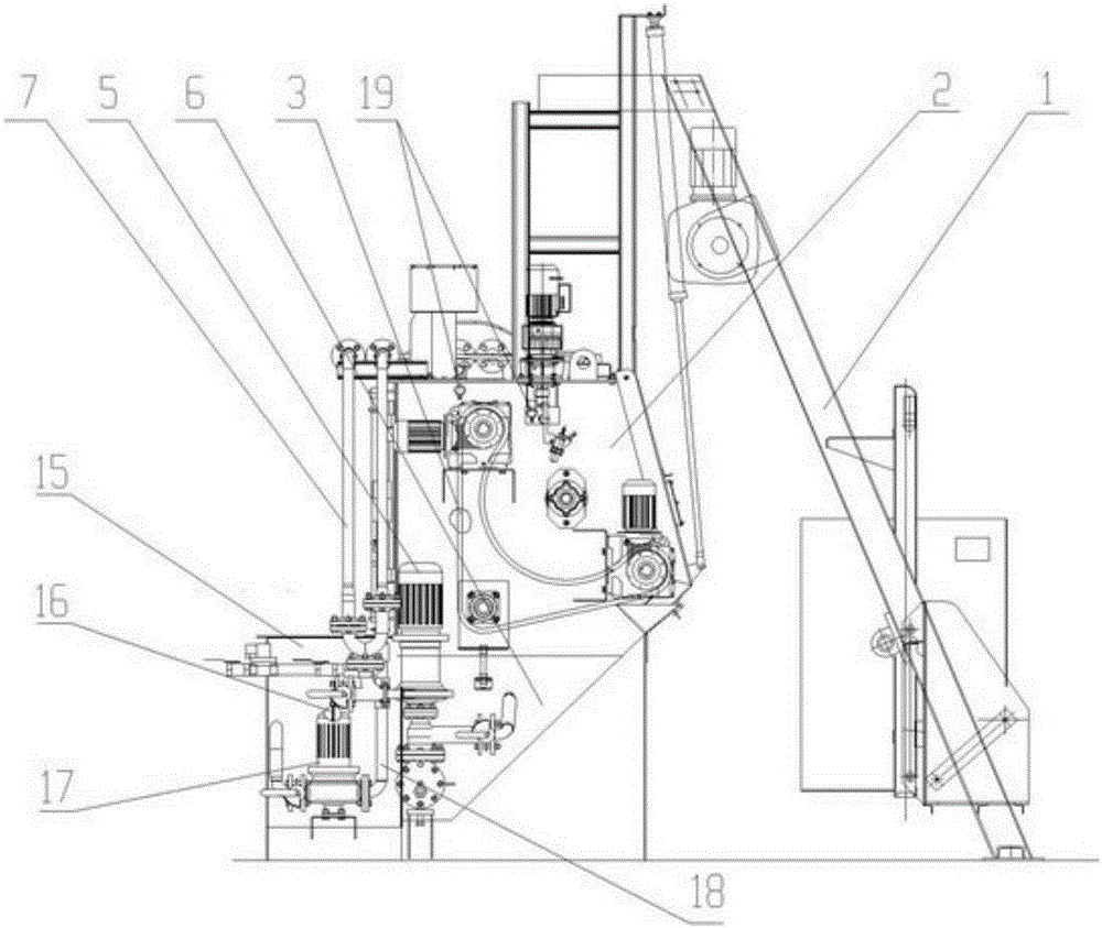
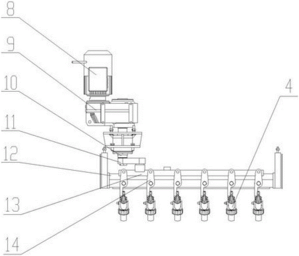
[0016] Depend on Figure 1-2 As can be seen from the shown embodiment, the present embodiment includes a feeding device 1 and a main body of a sandblasting machine. A cleaning chamber 2 is arranged in the main body of the sandblasting machine, and a carrier 3 of workpieces to be cleaned and a plurality of workpieces to be cleaned are arranged in the cleaning chamber. The sandblasting spray gun 4, the abrasive liquid pump 5 transports the abrasive liquid in the abrasive liquid storage tank 6 to the sandblasting spray gun 4 through the abrasive liquid delivery pipe 7, and a plurality of sandblasting spray guns 4 are installed on the spray gun swing mechanism, and the spray gun swing mechanism includes The drive device and the horizontal swing device, the drive device includes a drive motor 8, the drive motor 8 is connected to the eccent...


PUM


Abstract

The invention discloses a wet type sand-blasting machine. The wet type sand-blasting machine comprises a feeding device and a sand-blasting machine body, wherein a cleaning chamber is arranged in the sand-blasting machine body; a carrier for a workpiece to be cleaned and a plurality of sand-blasting spray guns for cleaning the workpiece to be cleaned are arranged in the cleaning chamber; a grinding fluid pump conveys grinding fluid in a grinding fluid storage tank to the sand-blasting spray guns through a grinding fluid conveying pipe; and the plurality of sand-blasting spray guns are arranged on a spray gun oscillating mechanism. The wet type sand-blasting machine also comprises a water cleaning device, wherein the water cleaning device comprises a sedimentation water tank; the sedimentation water tank and the grinding fluid storage tank are separated by one, two or more filter screens, so that the grinding fluid can be filtered to obtain clean washing water and the clean washing water is stored in the sedimentation water tank; and a washer pump conveys the washing water to a washing spray gun through a washing water conveying pipe to wash the workpiece and the cleaning chamber. The wet type sand-blasting machine has the characteristics that the production cost is low; the surface of the workpiece is processed perfectly; the dust-removing effect is good; and energy conservation and emission reduction are realized.

Description

technical field [0001] The invention relates to a sandblasting machine. Background technique [0002] Sand blasting machine is used to clean the scale, residual salt and welding slag of heat treatment parts, welding parts, castings, forgings, etc.; clean the tiny burrs and surface residues of machined parts; change the surface roughness of workpieces; renovate old parts, etc. The currently used sandblasting machine, the sandblasting spray gun adopts a fixed installation method. When the sandblasting machine is in operation, the sandblasting spray gun forms fixed-point spraying. Since the spraying range is relatively fixed, a spraying dead angle is formed. Some parts of the workpiece cannot be sprayed, which affects the quality of the workpiece. The quality of surface treatment, in order to spray as much as possible on the surface of the workpiece, we can only place fewer workpieces in the cleaning room, and the sandblasting machine processes fewer workpieces each time. If it...

Claims


Application Information

Patent Timeline
Patent Type & Authority Applications(China)
IPC IPC(8): B24C1/08B24C5/02B24C3/04B24C9/00B24C3/12B08B3/02
CPCB08B3/02B24C1/086B24C3/04B24C3/12B24C5/02B24C9/00
Inventor 李彦青吴瑞敏
Owner 永红保定铸造机械有限公司
Why Eureka
Try Eureka