Convenient-to-move bracket for steel pipe processing

A technology of brackets and steel pipes, which is applied in the direction of external frames, manual conveying devices, packaging, etc., can solve the problems of not having center height adjustment, affecting the processing progress of steel pipes, and affecting the processing accuracy of steel pipes, so as to achieve convenient alignment, simple structure, The effect of reducing the coefficient of friction

Inactive Publication Date: 2017-01-04
扬州巨业耐磨复合材料有限责任公司
0 Cites 4 Cited by

AI-Extracted Technical Summary

Problems solved by technology

[0002] The use of ordinary steel pipes is more common in daily life. In special industries such as electric power, metallurgy, mining, coal, petrochemical, etc., in order to meet the requirements of its diameter, wear resistance, corrosion resistance, high (low) temperature resistance, etc., it is necessary to provide some steel pipes with Steel pipes with special properties, and these steel pipes require special processing or treatment. Taking the processing of large-diameter steel pipes as an example, the processing of such steel pipes requires the use of brackets. After the steel pipes are placed...

Method used

As shown in Figure 1, the steel pipe processing bracket that is convenient to move, base is the frame structure that is formed by cross bar 6, vertical bar 5 and adjustment bottom bar 3 weldings, and 3 pairs of universal rollers are installed at frame structure bottom 6. Due to the heavy quality of the steel pipe, the caster of the universal roller 6 is an all-iron structure, which increases the strength of the universal roller; the horizontal bar 6 is a square steel pipe structure, and the vertical bar 5 is a channel steel structure; the idler seat 8 is a groove Steel structure, the opening of the channel steel is downward, and the number of idler seats 8 is 3 pairs. Each pair of idler seats 8 is welded to form a V-shaped angle of 45°, and a screw 4 ...

Abstract

The invention discloses a convenient-to-move bracket for steel pipe processing, and belongs to the technical field of mechanical manufacturing. Cross rods, vertical rods and regulating bottom rods are welded with one another to form a base; universal wheels are arranged below the base; two carrier roller bases and screws are welded to form Y-shaped structures; regulating devices are further arranged on the screws; two carrier roller end bases are welded above each carrier roller base; a carrier roller shaft is arranged between the carrier roller end bases; carrier rollers are idly arranged on the carrier roller shaft in a sleeved manner; a lifting rod is welded below each carrier roller base; and each lifting rod movably acts on each vertical rod. The convenient-to-move bracket meets a basic function of a steel pipe bearing, realizes fine adjustment of a height direction, and brings convenience in aligning center height of a steel pipe and center height of processing equipment; and the carrier rollers are arranged on the carrier roller shaft, and the steel pipe is in direct contact with the carrier rollers, so that the conventional sliding friction is changed into rolling friction, a friction coefficient is reduced, operations are convenient and labor-saving, steel pipe processing process flow is optimized, steel pipe processing progress is improved, and steel pipe processing precision is also improved.

Application Domain

External framesManual conveyance devices

Technology Topic

Base functionFriction coefficient +1

Image

  • Convenient-to-move bracket for steel pipe processing

Examples

  • Experimental program(1)

Example Embodiment

[0015] The present invention will be further described below in conjunction with accompanying drawing:
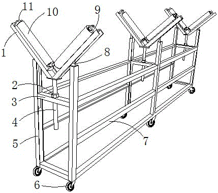
[0016] like figure 1 As shown, the bracket for steel pipe processing that is easy to move includes a base and supporting rollers 10, and the base is formed by welding a cross bar 7, a vertical bar 5, and an adjustment bottom bar 3, and a universal wheel 6 is provided under the base. The roller seat 1 and the screw 4 are welded to form a Y-shaped structure. There is a through hole in the middle of the adjustment bottom rod 3, and the screw 4 is movably connected in the through hole. An adjustment device 2 is also provided on the screw 4. There are two idler end seats 9 welded on the top of the idler seat 9, and an idler shaft 11 is arranged between the idler end seats 9, and the idler 10 is emptied on the idler shaft 11, and the bottom of each idler seat 1 is welded with a lift Rod 8, elevating rod 8 activities act in the vertical rod 5.
[0017] like figure 1 As shown, the bracket for steel pipe processing is easy to move. The base is a frame structure formed by welding the horizontal bar 6, the vertical bar 5 and the adjustment bottom bar 3. Three pairs of universal rollers 6 are installed at the bottom of the frame structure. Due to the quality of the steel pipe Heavier, the casters of the universal roller 6 are all-iron structure, which increases the strength of the universal roller; the horizontal bar 6 is a square steel pipe structure, the vertical bar 5 is a channel steel structure; the idler seat 8 is a channel steel structure, and the channel steel opening Downward, the number of idler seats 8 is 3 pairs, and each pair of idler seats 8 is welded to form a V-shaped angle of 45°, and a screw 4 is welded at the lower end of the V-shaped, and each pair of idler seats and the screw are welded to form a Y-shaped, A lifting rod 7 is welded under the middle of each idler seat, and the upper end of the lifting rod 7 is welded in the groove of the channel steel. The adjusting device 2 is a hexagonal nut. The hexagonal nut is screwed and connected with the screw rod 4 and placed on the bottom rod 3; adjust the diameter of the through hole on the bottom rod 3 to be slightly larger than the outer diameter of the screw 4; the idler end seat 8 is perpendicular to the idler seat 1, and the idler shaft 10 is parallel to the idler seat 1; the lifting rod 7 is the optical axis structure, the lifting rod 7 acts in the groove of the vertical rod 5.
[0018] like figure 1 As shown, the steps to use the mobile bracket for steel pipe processing are as follows: loosen the locking device on the universal roller, push the bracket to the place to be processed under the action of the universal roller, and lock the universal roller. Locking device: hoist the steel pipe with a truss crane and place it on the bracket, and the steel pipe is supported by the bracket, and the adjusting nut is pulled with a manual wrench, the nut rotates in situ, and the linear motion of the screw rod drives up and down. The bracket is fine-tuned up and down, and the adjustment of the bracket causes the change of the center height of the steel pipe. Therefore, when the center height of the steel pipe needs to be equal to the center of rotation of the equipment, it is only necessary to adjust the adjustment nuts under the three pairs of brackets respectively; The idler is sleeved on the idler shaft, so the idler can rotate relative to the idler shaft. When the steel pipe needs to be moved, the previous sliding friction is changed to rolling friction, which reduces the friction coefficient and facilitates the processing of the steel pipe.

PUM

no PUM

Description & Claims & Application Information

We can also present the details of the Description, Claims and Application information to help users get a comprehensive understanding of the technical details of the patent, such as background art, summary of invention, brief description of drawings, description of embodiments, and other original content. On the other hand, users can also determine the specific scope of protection of the technology through the list of claims; as well as understand the changes in the life cycle of the technology with the presentation of the patent timeline. Login to view more.

Similar technology patents

Air bag module

InactiveUS20070057487A1simple structureeasily manufacture
Owner:HYUNDAI MOBIS CO LTD

Biometric identification apparatus

InactiveUS20080037001A1perform accurately and rapidlysimple structure
Owner:HITACHI MEDIA ELECTORONICS CO LTD

Body condition measuring device

InactiveUS20050234351A1simple structure
Owner:DENSO CORP

Classification and recommendation of technical efficacy words

  • Simple structure
  • Working principle is clear

Sharing system for air-conditioning coat

InactiveCN107440179ASimple structureeasy to wear
Owner:QINGDAO HAIER AIR CONDITIONER GENERAL CORP LTD

Feeding device of sorter of batteries plate

InactiveCN101357717ASimple structurecooperate well
Owner:NANJING NORMAL UNIVERSITY

Emergency parachuting device and method for multiple-rotor unmanned aerial vehicle

InactiveCN103895870Aavoid aircraft crashSimple structure
Owner:SOUTH CHINA AGRI UNIV +1

Quick pipe connector

Owner:YANG RICHARD

Parallel-connection three-dimensional force sensor with decoupling structure

InactiveCN101907502ASimple structureWorking principle is clear
Owner:YANSHAN UNIV

Marking method for defective products of radio frequency tags

ActiveCN106218235ASimplify operation stepsWorking principle is clear
Owner:ARIZON RFID TECH YANGZHOU

Convenient counter top electric fryer provided with oil drain valve

PendingCN106974563ASimple structureWorking principle is clear
Owner:YANGZHOU HAI NIU KITCHEN EQUIP CO LTD

Self-adaptive height-adjustable fruit cleaning device

InactiveCN106473194ASimple structureWorking principle is clear
Owner:王华

Underground structure for active shock absorption

PendingCN109653257ASimple operating systemWorking principle is clear
Owner:AVIC GEOTECHN ENG INST
Why Eureka
Try Eureka