lobe evacuator

A lobe and nozzle technology, which is applied in the field of lobe evacuators, can solve the problems such as the lack of research to improve the ejection coefficient and evacuation efficiency of the steam ejector, the small steam consumption, the large steam consumption, etc., so as to increase the effective contact and entrainment area. , The effect of improving the flow shape and increasing the effective contact area

Inactive Publication Date: 2018-10-12
苏州中尧节能环保设备有限公司
View PDF6 Cites 0 Cited by
  • Summary
  • Abstract
  • Description
  • Claims
  • Application Information

AI Technical Summary

Problems solved by technology

The larger the diameter of the nozzle throat, the larger the steam consumption, and the smaller the diameter of the nozzle throat, the smaller the steam consumption. Howeve

Method used


Image

  • lobe evacuator
  • lobe evacuator

Examples


Embodiment Construction

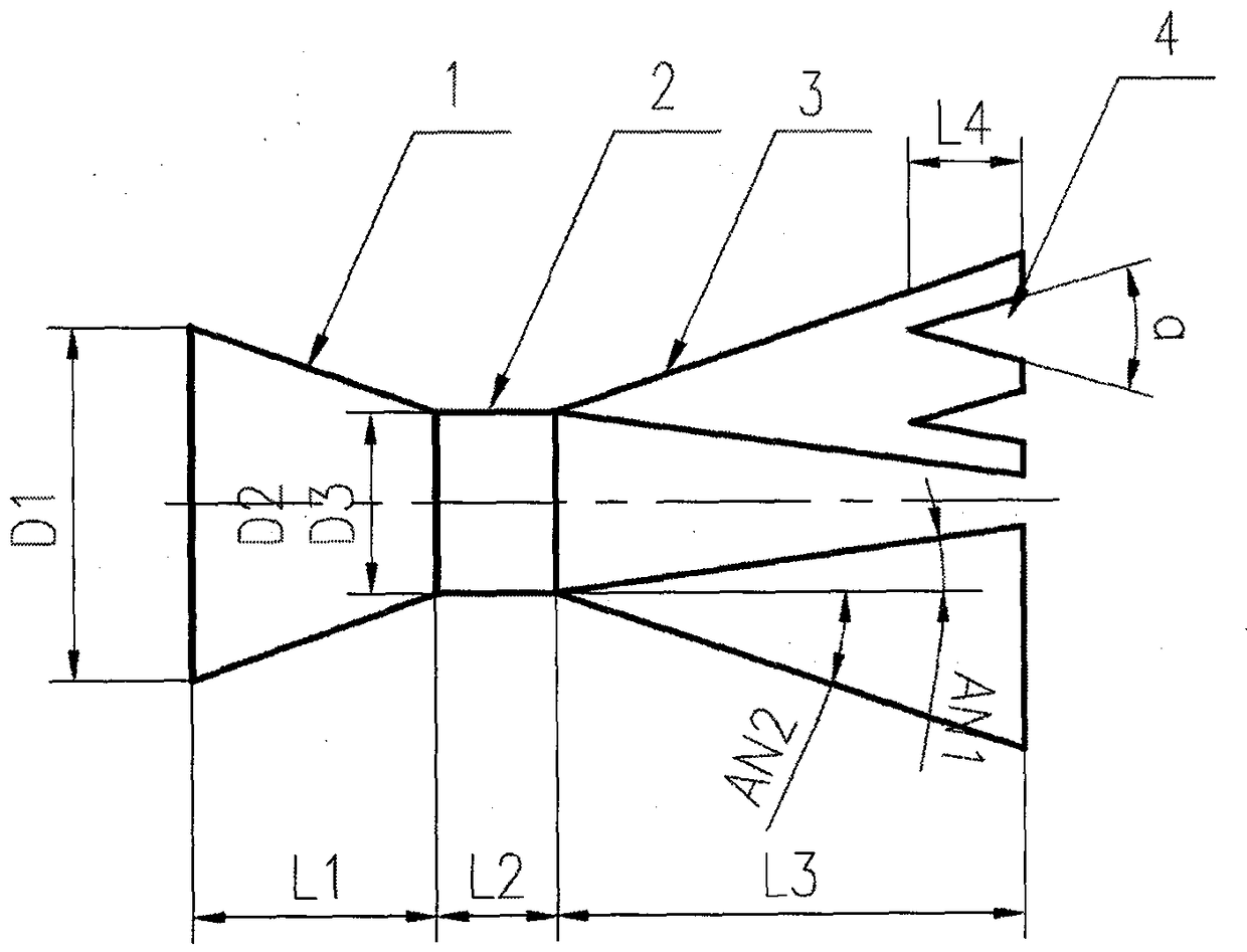
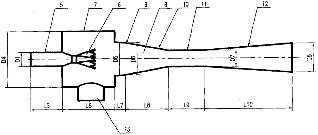
[0019] figure 1 and figure 2 A supersonic lobe nozzle and a lobe evacuator device equipped with the supersonic lobe nozzle are shown. Will figure 1 The 3 parts of the medium lobe nozzle: the nozzle inlet section ( figure 1 Symbol 1), nozzle throat ( figure 1 Symbol 2), nozzle outlet section ( figure 1 Symbol 3) are connected in sequence to form a complete supersonic lobe nozzle structure. Then, the complete supersonic lobe nozzle ( figure 2 Symbol 6) is installed in the suction chamber ( figure 2 In symbol 7), the inlet section of the lobe nozzle ( figure 1 Symbol 1) and the inlet section of the mainstream fluid (such as water vapor, air, process fluid) pipeline ( figure 2The joints in symbol 5) are welded, or gasketed and threaded, or gasketed and flanged, and the process piping that needs to be sucked in the process device is welded, or gasketed and threaded, or gasketed Plate seal and flanged to the secondary inlet ( figure 2 Middle symbol 13), the outlet of ...


PUM


Abstract

The invention discloses a supersonic speed lobe nozzle and a lobe pumping-out device with the nozzle. The supersonic speed lobe nozzle comprises an inlet segment, a nozzle throat portion and a nozzle outlet segment, and nozzle outlet tail edge modification is carried out. The lobe pumping-out device with the supersonic speed lobe nozzle comprises a main current fluid pipeline inlet segment, the supersonic speed lobe nozzle, a suction chamber, a secondary flow inlet connected with the suction chamber and a mixed pressure expanding chamber. The mixed pressure expanding chamber comprises a mixing segment composed of an inlet portion and a convergence portion, a throat portion and a pressure expanding segment. The high injection coefficient and the high work efficiency are thoroughly and mechanically achieved, energy can be greatly saved, and consumption can be greatly reduced.

Description

technical field [0001] The invention belongs to the technical fields of petroleum, petrochemical, chemical, metallurgy, electric power, refrigeration, pharmaceutical, seawater desalination and other industry equipment, and in particular relates to a supersonic lobe nozzle and a lobe evacuator device for generating vacuum. [0002] Furthermore, the invention relates to a jet pump for conveying fluids. [0003] Furthermore, the invention relates to an ejector vacuum pump for generating a vacuum. Background technique [0004] The existing evacuator is made of a fluid medium with a certain pressure and temperature, such as steam, air, and device process fluid (called the main flow). Energy exchange and mixing with the pumped medium (called secondary flow) is carried out in the mixing and diffusing chamber, and the pumped medium is mixed, decelerated, and pressurized in the mixing and diffusing chamber, and finally discharged against the outlet back pressure, so as to achieve se...

Claims


Application Information

Patent Timeline
IPC IPC(8): F04F5/00
Inventor 刘宏友
Owner 苏州中尧节能环保设备有限公司
Why Eureka
Try Eureka