Supercharge Your Innovation With Domain-Expert AI Agents!

Design and manufacturing method of special hot-water boiler for burning hot gas of generator

A technology for hot water boilers and manufacturing methods, applied to lighting and heating equipment, water heaters, fluid heaters, etc., can solve the problems of large pollutant discharge, dispersion, and lack of conventional gas sources, etc., to achieve sufficient combustion and reduce The effect of emissions

Inactive Publication Date: 2017-01-04
刘俊杰 +1
View PDF5 Cites 0 Cited by
  • Summary
  • Abstract
  • Description
  • Claims
  • Application Information

AI Technical Summary

Problems solved by technology

[0008] The object of the present invention is to propose a hot water boiler specially used for burning generator hot gas in order to overcome the shortcomings of current coal-fired industrial boilers, such as high energy consumption, low efficiency, and large pollutant discharge. Nearby one-to-one combined application solves the practical problems of tens of thousands of small towns and rural areas with wide, scattered heating and lack of conventional gas sources, and makes up for the market demand of eliminated coal-fired boilers

Method used


Image

  • Design and manufacturing method of special hot-water boiler for burning hot gas of generator
  • Design and manufacturing method of special hot-water boiler for burning hot gas of generator
  • Design and manufacturing method of special hot-water boiler for burning hot gas of generator

Examples


Embodiment 1

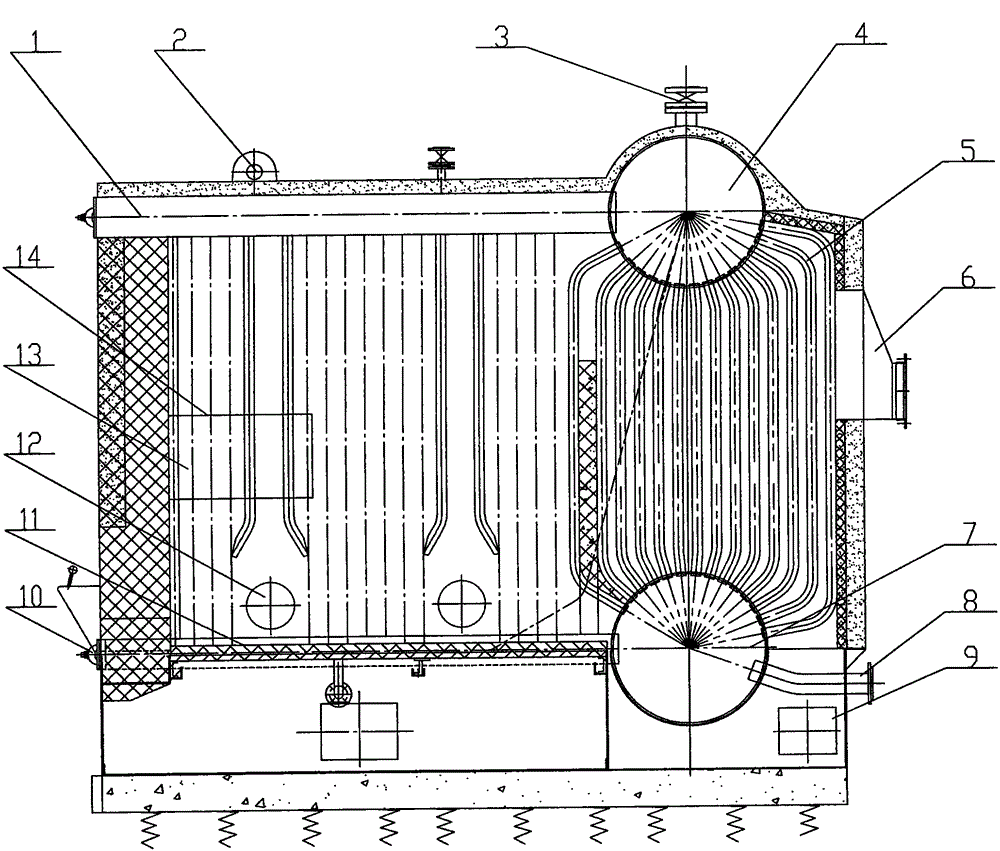
[0030] Attached figure 1 One end of the header tube (1) on the furnace shown in the furnace is perforated and inserted into the drum (4), the upper end of the convection tube bundle (5) is bent and inserted into the upper drum (4), and the convection tube bundle (5) ) is bent and inserted into the lower drum (7) for welding, the upper heads of the water-cooled wall tubes (13) on both sides of the furnace are punched and welded with the upper header (1) of the furnace, and the lower heads are respectively connected with the left and right lower headers figure 2 The middle (15, 25) is perforated and inserted into welding, and the water wall tube (13) on the right side and the lower header figure 2 The top of middle (25) leaves burner installation hole (12) and leaves secondary burner installation hole (14) in the left side middle lower part of left side water-cooled wall pipe (13).

Embodiment 2

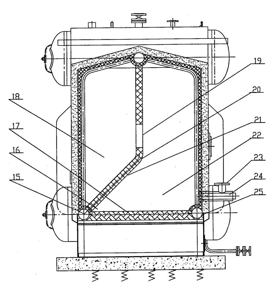
[0032] with attached figure 2 The upper head of the water-cooled wall pipe (20) in the middle of the shown furnace and the upper header of the furnace figure 1 (1) is perforated and inserted into welding, bent at 1 / 3 of the middle and lower end, the lower head and the left lower header (15) are perforated and inserted into welding, and the entire furnace is divided into two to form two combustion chambers (22 , 18), an alpha angle (16) is formed at the connection point between the lower end of the middle water wall tube (20) and the left lower header (15) and the surface of the furnace bottom (17) heat storage radiation layer, the hypotenuse of the alpha angle Constitute the flame refraction arch (21) of the main combustion chamber.

[0033] There is a high-temperature flue gas channel (19) above the 1 / 3 bend of the middle water wall tube (20), when the combustible gas enters the combustion nozzle (24) and the primary air (23) is mixed at the combustion nozzle mouth , the c...

Embodiment 3

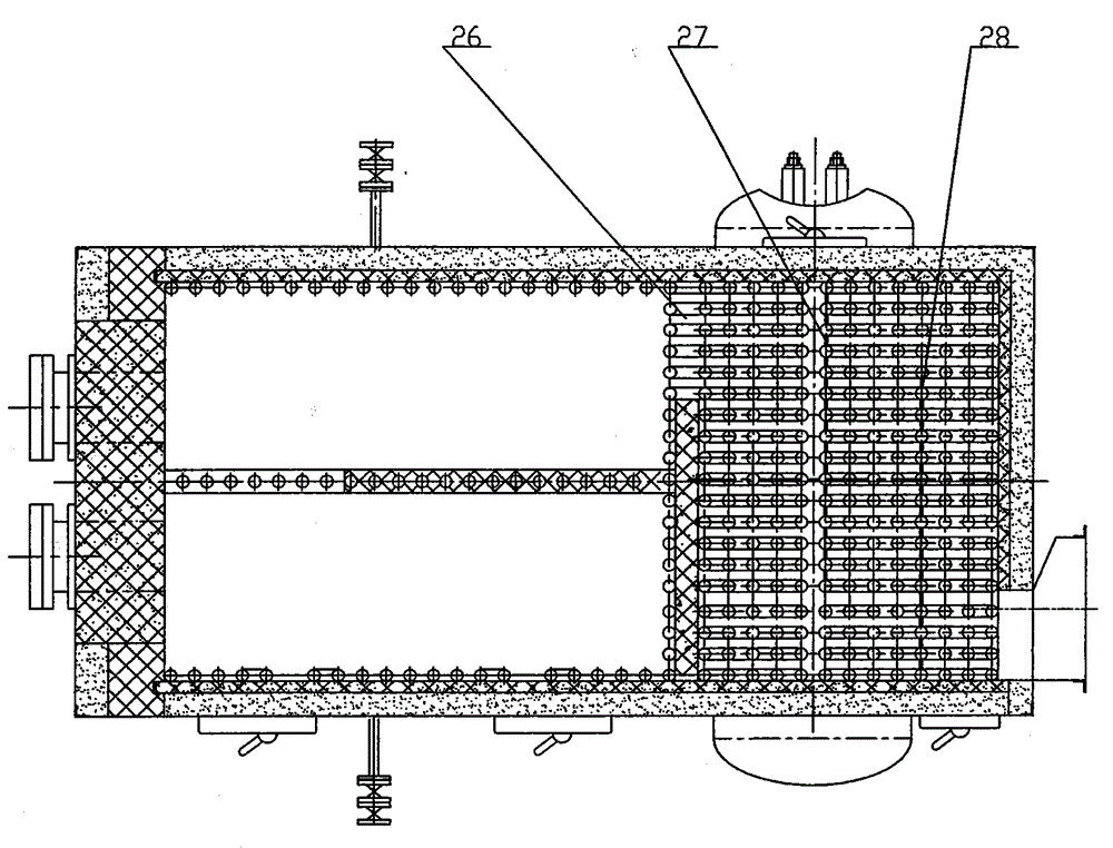
[0035] with attached image 3 As shown, after the secondary combustion chamber figure 2 The high-temperature flue gas after secondary combustion in (18) enters through the exhaust channel (26) figure 1 The middle convection tube bundle (5) is provided with two smoke baffles (27, 28) in the middle of the convection tube bundle (5). After a return convective heat exchange, the figure 1 The middle smoke outlet (6) is discharged.


PUM


Abstract

The invention provides a design and manufacturing method of a special hot-water boiler for burning hot gas of a generator and aims to change an outdated fuel burning manner of fire coal fundamentally and change a solid fuel burning manner to a gas burning manner. The method is characterized in that a method of the double-burning-chamber design is adopted, that is, a main burning chamber and an auxiliary burning chamber are designed, on the basis that the design of a furnace structure of a coal-fired boiler is used for reference, a row of water wall tubes are added in the middle of the furnace by the aid of an upper header and a lower header on the left side, the furnace is divided into two parts, two burning chambers are formed, the 1 / 3 position of the lower end of the middle water wall tube is bent, the lower end of the middle water wall tube is connected with the lower header on the left side, an alpha angle of the main burning chamber is formed by the connecting point and the surface of a heat accumulation radiation layer at the bottom, a smoke channel is reserved at the upper middle end of the middle water wall tube, other parts are completely sealed with refractory cement, the slope of the alpha angle form a flame refraction arch, when gas is burnt, flames spit by a nozzle are directly laid on the refraction arch and are refracted, and a fire backflow burning area is formed in the position.

Description

[0001] Technical field: [0002] The invention relates to a design and manufacture method specially used for burning generator hot gas and hot water boilers, in particular to a method combined with a gas generator. [0003] Background technique: [0004] Boilers are important energy conversion equipment. By the end of 2012, the total number of coal-fired industrial boilers in use in my country reached 467,000 units, with a total capacity of 1.78 million steam tons. It is a large energy consumer and an important source of air pollution. The capacity of most coal-fired industrial boilers Smaller, the average capacity of a single unit is only 3.8t / n, of which the number of units below 2t / n accounts for 66.5%, and the actual operating thermal efficiency is only 60%-65%, which is about 15 percentage points lower than the international advanced level. Coal-fired The biggest disadvantages of industrial boilers are high energy consumption, incomplete combustion, high pollutant emission i...

Claims


Application Information

Patent Timeline
IPC IPC(8): F24H1/40F24H9/18
Inventor 刘俊杰
Owner 刘俊杰
Features
  • R&D
  • Intellectual Property
  • Life Sciences
  • Materials
  • Tech Scout
  • Unparalleled Data Quality
  • Higher Quality Content
  • 60% Fewer Hallucinations
Learn More