
Method for designing novel mesh antenna structure with shaped pattern

A beam-forming and antenna structure technology, applied in the field of radar antennas, can solve the problems of complicated design process and limited shaping ability.

Active Publication Date: 2017-01-04
XIDIAN UNIV
View PDF3 Cites 18 Cited by
  • Summary
  • Abstract
  • Description
  • Claims
  • Application Information

AI Technical Summary

Problems solved by technology

The design process of this method is complicated, and the shaping ability is very limited

Method used


Image

  • Method for designing novel mesh antenna structure with shaped pattern
  • Method for designing novel mesh antenna structure with shaped pattern
  • Method for designing novel mesh antenna structure with shaped pattern

Examples


Embodiment Construction

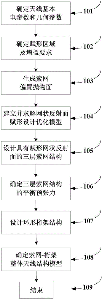
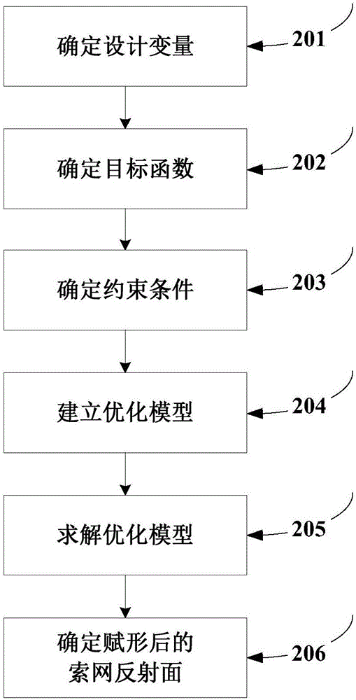
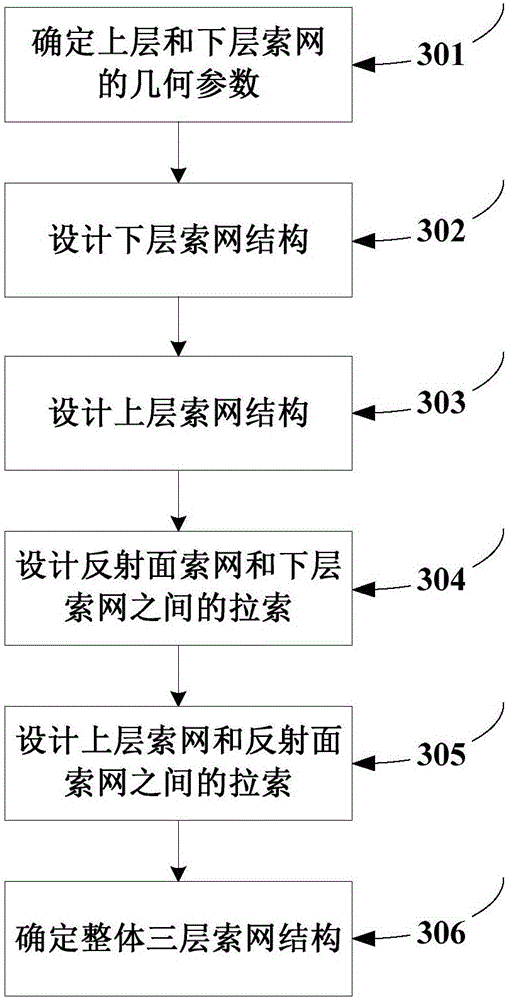
[0080] Such as figure 1 As shown, the present invention provides a novel mesh antenna structure design method with shaped beams, which is achieved by expanding the two-layer cable-net structure of the surrounding truss-type deployable mesh antenna into a three-layer cable-net structure. The design method of the mesh antenna structure of the shaped reflector comprises the following steps:

[0081] Step 101: Determine the basic electrical parameters and geometric parameters of the mesh antenna reflector, including: the operating frequency f of the antenna, the optical aperture D of the antenna, the focal length F of the reflector, the offset distance p of the reflector, and the height H of the antenna;

[0082] Step 102: Determine the antenna far-field observation point (AZ i ,EL i ) and the gain requirement D of the shaped region i ≥D obj (i=1~N far ); where (A-Z i ,EL i ) represents the angular coordinates of the i-th far-field observation point, where AZ represents the...


PUM


Abstract

The invention discloses a method for designing a novel mesh antenna structure with a shaped pattern. The method comprises the steps of conducting shape design on a reflective surface of an antenna cable net firstly; then designing the cable net structures of an upper layer and a lower layer according to the shaped meshed reflective surface, so that an overall three-layer cable net structure is obtained; conducting pretension balancing design on the three-layer cable net structure so as to guarantee the tensile property and realizability of the structure; designing a three-layer truss structure supporting the three-layer cable net finally, so that a cable net-truss overall antenna structure is obtained. By extending a two-layer cable net structure of a peripheral truss type extendable mesh antenna into the three-layer cable net structure, the mesh antenna structure with the shaped reflective surface is obtained, and the design process is simple; the designed shaped mesh antenna structure is tensile, easy to realize and high in engineering application value.

Description

technical field [0001] The invention belongs to the technical field of radar antennas, and in particular relates to a novel mesh antenna structure design method with shaped beams, which is applied to the shaped beam design of spaceborne mesh antennas. Background technique [0002] The shaped reflector antenna has the characteristics of high efficiency and low signal interference in the adjacent area of ​​the service area, and is widely used in satellite communications; at the same time, the surrounding truss-type deployable mesh antenna has the characteristics of light weight, small volume and short period , has become a form of space deployable antenna that has attracted the attention of the aerospace community in recent years; therefore, it is necessary to study how to realize the shaped beam design of the mesh reflector based on the surrounding truss-type deployable antenna structure. [0003] The peripheral truss-type deployable mesh antenna has become a form of space-de...

Claims


Application Information

Patent Timeline
Patent Type & Authority Applications(China)
IPC IPC(8): G06F17/50
CPCG06F30/20G06F2111/10
Inventor 张逸群杨癸庚段宝岩杨东武李申杜敬利张树新
Owner XIDIAN UNIV
Learn More