Antenna and RF signal transceiver

A technology for radio frequency signals and transceivers, which is applied to the field of antennas and radio frequency signal transceivers including the antennas, and can solve the problems of radio frequency signals that are difficult to enlarge and shrink due to the size of the antenna

Active Publication Date: 2019-06-11
WISTRON NEWEB
View PDF9 Cites 4 Cited by
  • Summary
  • Abstract
  • Description
  • Claims
  • Application Information

AI Technical Summary

Problems solved by technology

[0003] The size of the antenna itself is limited by the length of the wavelength of the corresponding radio frequency signal. It is usually difficult to zoom in and out.

Method used


Image

  • Antenna and RF signal transceiver
  • Antenna and RF signal transceiver
  • Antenna and RF signal transceiver

Examples


Embodiment Construction

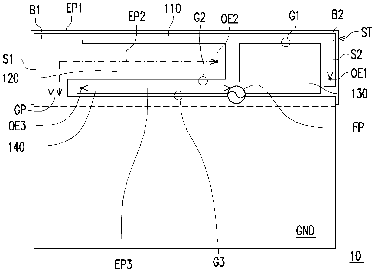
[0042] figure 1 It is a schematic structural diagram of an antenna according to an embodiment of the present invention. Please refer to figure 1 , in this embodiment, the antenna includes an antenna structure 10 disposed on a substrate ST. The antenna structure 10 includes a ground plane GND, a first radiating part 110 , a second radiating part 120 , a metal coupling part 130 , a third radiating part 140 and a feeding point FP. The ground plane GND includes a ground point GP. In this embodiment, the first radiating portion 110 presents a U-shape and has a first bend B1 , a second bend B2 and an open end OE1 . The first radiating portion 110 extends from the ground point GP, and the open end OE1 of the first radiating portion 110 is adjacent to the ground plane GND.

[0043] The second radiating part 120 has an open end OE2, and radiates from the section between the first bend B1 of the first radiating part 110 and the ground point GP (that is, the first section S1 of the f...


PUM


Abstract

The invention provides an antenna and a radio-frequency signal transmit-receive device. The antenna comprises a substrate and an antenna structure arranged on the substrate. The antenna structure comprises a grounding plane, a first radiation portion, a second radiation portion, a metal coupling portion, a third radiation portion and a feed-in point. The grounding plane comprises a grounding point; the first radiation portion has first bending, second bending and an open end; the first radiation portion extends from the grounding point, and the open end of the first radiation portion is adjacent to the grounding plane; the second radiation portion extends from the section between the first bending point of the first radiation portion and the grounding point to the section between the second bending of the first radiation portion and the open end; the metal coupling portion is adjacent to the grounding plane, the second bending and the open end of the first radiation portion as well as the second radiation portion; the third radiation portion is arranged between the second radiation portion and the grounding plane and extends from the metal coupling portion to the section between the first bending of the first radiation portion and the grounding point; and the feed-in point is coupled at the connection place of the third radiation portion and the metal coupling portion. The radio-frequency signal transmit-receive device can receive and send a plurality of radio-frequency signals of a plurality of frequency bands.

Description

technical field [0001] The present invention relates to an antenna and a radio frequency signal transceiving device, and in particular to an antenna and a radio frequency signal transceiving device comprising the antenna. Background technique [0002] With the rapid development of technology, mobile electronic devices, such as smart phones and tablet computers, are widely present in people's lives. Generally speaking, a mobile electronic device is equipped with a radio frequency signal transceiver module and its corresponding antenna structure, so that the mobile electronic device has the radio frequency signal transceiving capability to meet the needs of the user of the mobile electronic device for communication and data transmission. The antenna structure on the mobile electronic device needs to be set corresponding to the frequency band and characteristics of the radio frequency signal to be sent and received, which may include one or more antennas to send and receive the...

Claims


Application Information

Patent Timeline
Patent Type & Authority Patents(China)
IPC IPC(8): H01Q1/48H01Q1/50H01Q1/36
Inventor 陈俊甫江毓彧
Owner WISTRON NEWEB
Why Eureka
Try Eureka