Trans-impedance amplifier

A technology of transimpedance amplifier and common gate, applied in amplifiers, differential amplifiers, DC-coupled DC amplifiers, etc., can solve problems such as large open-loop gain, large size, and bandwidth limitations

Inactive Publication Date: 2017-01-04
UNIV OF ELECTRONICS SCI & TECH OF CHINA
View PDF6 Cites 13 Cited by
  • Summary
  • Abstract
  • Description
  • Claims
  • Application Information

AI Technical Summary

Problems solved by technology

[0005] Combining the above two transimpedance amplifier structures, we can see that the op amp-based transimpedance amplifier has a large open-loop gain, but the bandwidth will be limited
The common-gate input structure is simple, but in order to reduce the input resistance, it means that the device must have a large size, or consume a large power consumption to obtain a high transconductance equivalently, which is necessary for high-performance integrated circuits. Avoided
Especially for the high bandwidth requirements of the baseband data rate, the circuit design requirements become more stringent

Method used


Image

  • Trans-impedance amplifier
  • Trans-impedance amplifier
  • Trans-impedance amplifier

Examples


Embodiment

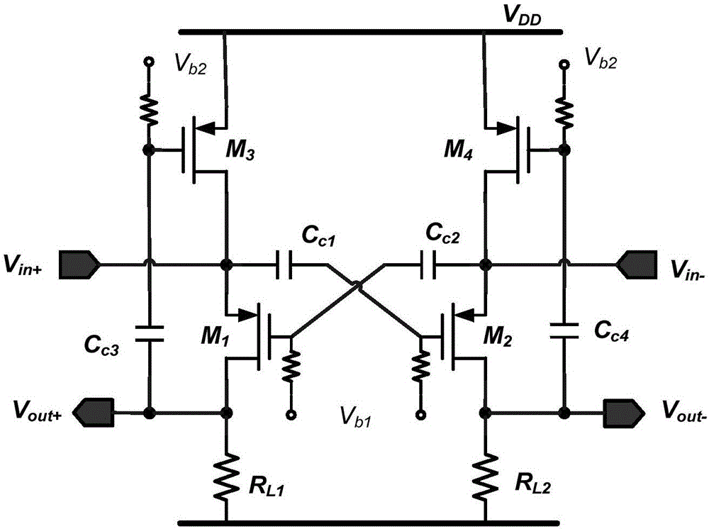
[0037] The transimpedance amplifier circuit provided in this embodiment is implemented using a 0.18 μm RF CMOS process, powered by a 1.8V power supply, and the static bias current of the circuit is only 1.19mA. Parameter Cc 1 、Cc 2 :10nF,Cc 3 、Cc 4 : 1nF, R L1 , R L2 : 1KΩ. Because the capacitance value is large, it can be realized by using off-chip components. Figure 4 Among them, the ordinate Zin represents the differential input impedance of the circuit, and the abscissa Frequency represents the typical baseband frequency, Figure 4 The input impedance simulation results of the transimpedance amplifier are given in , it can be seen that the differential input impedance of the circuit is only 33.8Ω at a typical baseband frequency of 1MHz. And in the baseband frequency range of 20MHz, the impedance is generally maintained in a lower range. Figure 5 Among them, the ordinate NF represents the noise figure, and the abscissa Frequency represents the typical baseband fre...


PUM


Abstract

The invention discloses a common-gate input type low-power-consumption trans-impedance amplifier and belongs to the field of integrated circuits. The amplifier is a differential input / output structure and comprises common-gate input levels, load levels and feedback levels. Radio frequency differential signals V<in+ / -> are input through the source ends of the common-gate input levels, are converted into signal currents, are further converted into voltage signals at the load levels and finally form output differential signals V<out+ / ->. The output voltage signals are sampled by the feedback levels and are fed back to the source ends of the common-gate input levels, thereby improving equivalent input transconductance. The common-gate input levels adopt capacitor cross-coupling modes, so that the equivalent input transconductance is further improved. According to the trans-impedance amplifier, the high-performance trans-impedance amplifier can be realized with relatively low power consumption.

Description

technical field [0001] The invention belongs to the field of integrated circuits, in particular to a design technology of a transimpedance amplifier. Background technique [0002] Currently, software radio technology compatible with multiple protocols is becoming more and more important. Correspondingly, the research and development of broadband radio frequency transceiver technology has become increasingly urgent. For a long time in the past, circuit designers have been accustomed to using voltage signal variables to analyze and characterize the characteristics of circuits, which is a concept of circuit design technology based on voltage modulus. In recent years, the potential advantages of current-mode circuits in analog / mixed-signal processing are gradually being tapped, and rapidly promote the development of circuit design techniques based on current-mode operations. At present, many breakthroughs have been made in the research of circuits operating in current mode in ...

Claims


Application Information

Patent Timeline
Patent Type & Authority Applications(China)
IPC IPC(8): H03F1/02H03F1/56H03F3/45
CPCH03F1/0211H03F1/56H03F3/45179H03F2203/45346
Inventor 郭本青陈俊
Owner UNIV OF ELECTRONICS SCI & TECH OF CHINA
Why Eureka
Try Eureka