A loudspeaker structure

A loudspeaker and basin frame technology, which is applied in the field of loudspeaker structure, can solve the problems of abnormal sound, elastic waves are easy to hit the screw head, and the screw hole is difficult to manufacture. , the effect of good music enjoyment experience

Active Publication Date: 2020-01-24
TYMPHANY HK
View PDF3 Cites 0 Cited by
  • Summary
  • Abstract
  • Description
  • Claims
  • Application Information

AI Technical Summary

Problems solved by technology

The disadvantage of screw fixing is that the small-caliber speaker (speaker) washer screw hole is too small, and the punching needle is easy to break when the mold is punched when processing the bottom hole; in addition, the screw head takes up space, and the speaker is easy to hit the screw head when it is working. abnormal sound
Due to the difficulty of manufacturing additional screw holes in Huasi, the loss of punching needles is high, which also increases the manufacturing cost and processing cost virtually.

Method used


Image

  • A loudspeaker structure
  • A loudspeaker structure
  • A loudspeaker structure

Examples


Embodiment 1

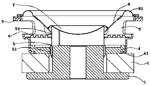
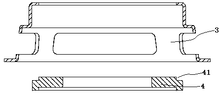
[0022] Such as Figure 1 ~ Figure 4 As shown, a new type of loudspeaker structure, including magnet 1, T iron 2, basin frame 3, washer 4, voice coil 5, elastic wave 6, dust cap 7, drum paper 8 and gasket 9, drum paper 8 is set There is a ring 81, the gasket 9 is located below the outer edge of the basin frame 3, the magnet 1 is located above the T iron 2, and a magnetic gap is formed between the washer 4 and the T iron 2, so The voice coil 5 is arranged in the magnetic gap, and the voice coil 5 includes a voice coil wire part 51 and a voice coil tube part 52; The outer side of the washer 4 is provided with a riveting groove 41 , and the washer 4 is riveted and fixed with the basin frame 3 through the riveting groove 41 . Compared with the two methods of fixing the washer and the pot frame by riveting joints and screw fixing, the new loudspeaker structure of the present invention stamps the outer side of the washer 4 by using a mold, so that the riveting groove 41 of the washe...

Embodiment 2

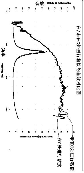
[0025] Traditionally, the voice coil tube portion 52 of the voice coil 5 is bonded and fixed to the dust cap 7 and the drum paper 8 during production of the speaker. Such as Figure 5 As shown, except the joint A between the voice coil tube part 52 and the dustproof cap 7 and the joint B between the voice coil tube part 52 and the drum paper 8, the new loudspeaker structure of the present invention is at the joint between the dustproof cap 7 and the drum paper 8 Gluing process is added to the joint C, and the dustproof cap 7 and the drum paper 8 are bonded together. Such as Figure 6 As shown, in the frequency range of 8000-20KHz, the curve response is smoother, the high-frequency hearing is more stable and smooth, and the glitch caused by the large fluctuation of the peak and valley of the curve is eliminated, and a good music enjoyment experience can be obtained.


PUM


Abstract

The invention discloses a novel loudspeaker structure, including magnets, T irons, basin frame, washers, voice coils, elastic waves, dust caps, drum paper and spacers, the drum paper is provided with rings, and the spacers are located on the basin frame Below the outer edge, the magnet is located above the T iron, and a magnetic gap is formed between Wasser and the T iron, and the voice coil is arranged in the magnetic gap, and the voice coil includes a voice coil wire part and a voice coil tube part; A riveting groove is provided on the outer side of the washer, and the washer is riveted and fixed to the pot frame through the riveting groove. The voice coil is respectively bonded and fixed to the dust cap and the drum paper at the voice coil tube, and the dust cap and the drum paper are also bonded and fixed. The new loudspeaker provided by the present invention, by setting riveting groove points on the outer side of the washer, and riveting tightly with the pot frame, not only reduces the overall height of the speaker, but also ensures more space for the elastic wave to descend, and ensures the pot frame The firmness of the connection ensures the safety of vibration and drop after the speaker is packed, and meets the application requirements of small-diameter speakers.

Description

technical field [0001] The invention relates to the technical field of acoustics, in particular to a loudspeaker structure. Background technique [0002] A speaker is an acoustic component used to complete the connection between electrical signals and sound signals, and has been widely used in electronic terminals such as televisions and audio systems. With the rapid development of portable Wifi, Bluetooth speakers, and ultra-thin TVs, such electronic products gradually tend to be ultra-thin and optimized structural design, so a series of stricter requirements are put forward for the speakers, requiring small diameter and thickness. Thin, high power, high sensitivity with solid structure and smooth acoustic response curve. [0003] Traditionally, there are two ways to fix the washer and the pot frame of the speaker. Method one: punch out a bump on the washer and rivet it with the hole of the pot frame; however, the washer used in the small-diameter speaker Generally, they ...

Claims


Application Information

Patent Timeline
Patent Type & Authority Patents(China)
IPC IPC(8): H04R9/06H04R9/02H04R31/00
CPCH04R9/02H04R9/06H04R31/006H04R1/22H04R7/127H04R9/045H04R2307/021H04R7/16H04R1/025H04R1/24H04R9/025H04R2209/022
Inventor 郭长林姚日成
Owner TYMPHANY HK
Why Eureka
Try Eureka