A profile and pipe cutting machine

A cutting machine and pipe technology, applied in metal processing, etc., can solve the problems of excessive sawdust, uneven cutting section, loud noise, etc., and achieve the effects of reducing sawdust pollution, low cost, and cutting loss

Active Publication Date: 2018-02-13
CHANGSHA KENBEI TECH
View PDF6 Cites 2 Cited by
  • Summary
  • Abstract
  • Description
  • Claims
  • Application Information

AI Technical Summary

Problems solved by technology

[0004] The technical problem to be solved by the present invention is: to overcome the deficiencies of the prior art, aiming at the problems of uneven cutting section, high noise and large amount of sawdust in the prior art, to provide a saw with simple structure, cost saving, strong cutting ability, and Profile and pipe cutting machine with less chips and less noise

Method used


Image

  • A profile and pipe cutting machine
  • A profile and pipe cutting machine
  • A profile and pipe cutting machine

Examples


Embodiment Construction

[0022] The present invention will be described in further detail below in conjunction with the accompanying drawings and embodiments.

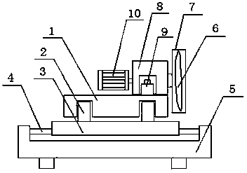
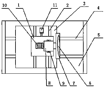
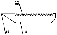
[0023] Such as Figure 1~4 Shown: a cutting machine for profiles and pipes, including a first base 5, a second base 3 and a cutting machine body 1, the first base 5 is provided with a slide bar 4, and the second base 3 can slide left and right on the slide bar 4 , the second base 3 is provided with a chute 2 for the cutting machine body 1 to slide back and forth and a positioning cylinder 11, the positioning cylinder 11 is connected with the cutting machine body 1, and the bottom of the cutting machine body 1 is provided with a chute on the second base 3 2 Form a sliding block that cooperates with sliding. The cutting machine body 1 is provided with a machine head 8, and both sides of the machine head 8 are provided with lifting cylinders 9. The machine head 8 is provided with a blade 6 and a rotating motor 10 that drives the blade 6 to rotate...


PUM


Abstract

The invention provides a cutting machine for profiles and pipes. The cutting machine comprises a first base, a second base and a cutting machine body. A sliding rod is arranged on the first base. The second base can slide leftwards and rightwards on the sliding rod. The second base is provided with a sliding groove used for forward and backward sliding of the cutting machine body, and a positioning air cylinder. The positioning air cylinder is connected with the cutting machine body. A sliding block which is in sliding fit with the sliding groove in the second base is arranged at the bottom of the cutting machine body. A machine head is arranged on the cutting machine body. Lifting air cylinders are arranged on the two sides of the machine head. Two blades and a rotating motor used for driving the blades to rotate are arranged on the machine head. A flat cutting edge and a sawtooth type cutting edge are formed on two corresponding sides of each blade correspondingly. A single-blade or double-blade sharp knife is arranged at one end of each blade. The two blades are fixedly arranged on a rotary shaft with the included angle between the two blades being 180 degrees, and the identical cutting edges of the two blades are in the same direction. A U-shaped silencing structure is arranged at the front end of the machine head. The cutting machine for profiles and pipes is simple in structure, capable of reducing cost, high in cutting capacity and low in nose, and little sawdust is generated.

Description

technical field [0001] The invention relates to the technical field of pipe and profile cutting equipment, in particular to a profile and pipe cutting machine. Background technique [0002] At present, the cutting machines used in plastic pipe, hose, and profile production lines are usually sheet cutting machines and chipless rotary cutting machines. These cutting methods can only cut profiles or pipes with relatively slow line speeds, which restricts the performance of the production line. , It is far from meeting the current demand for increasing product output. [0003] At present, the cutting method used in the market, during the cutting process, the saw teeth will damage the surface of the profile, and the unevenness of the incision will affect the quality of the finished profile; Vacuum cleaners or dust bags are used to collect sawdust, but it still cannot avoid the pollution of a large amount of sawdust to profiles and the environment. Falling on the motor will caus...

Claims


Application Information

Patent Timeline
Patent Type & Authority Patents(China)
IPC IPC(8): B26D1/28B26D5/04B26D5/00B26D7/22
CPCB26D1/0006B26D1/28B26D5/00B26D5/04B26D7/22B26D2001/0033B26D2001/0053B26D2001/006
Inventor 陶钢
Owner CHANGSHA KENBEI TECH
Why Eureka
Try Eureka