

Brake by wire system with hydraulic power and control method of brake by wire system
Patent Information
- Authority / Receiving Office
- CN · China
- Current Assignee / Owner
- WUHU BETHEL AUTOMOTIVE SAFETY SYST
- Publication Date
- 2017-01-11
Smart Images
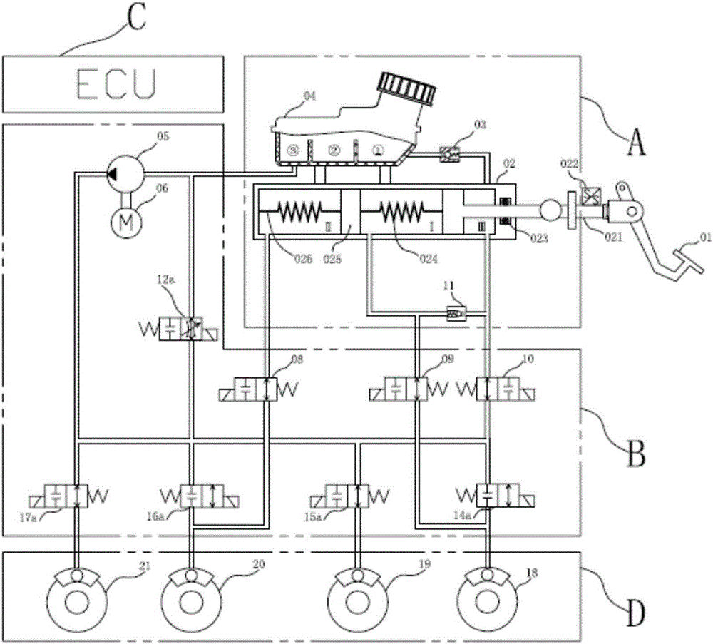
Figure 1 
Figure 2 
Figure 3
Abstract
Description
technical field
[0001] The invention belongs to the technical field of automobile brake systems. More specifically, the present invention relates to brake-by-wire systems with hydraulic assist. In addition, the present invention also relates to a control method of the above braking system. Background technique
[0002] The boost of the traditional automobile braking system is to use the vacuum generated by the engine or the vacuum generated by the electronic vacuum pump to realize the brake pressure build-up in the vacuum booster. Such as Figure 22 Shown, serial number 4 is described vacuum booster. When the driver brakes, the brake pedal 6 is stepped on, and the brake master cylinder 3 is driven to pass through the electronically controlled pressure regulating unit ABS / ESC2 to build up pressure on the brake 1 to generate brake fluid pressure; a vacuum booster is needed for the pedal during this process. The force is proportionally amplified, so that the driver can achie...