Axial-flow type adjusting valve

A regulating valve, axial flow technology, applied in sliding valves, valve details, safety valves, etc., can solve problems such as slow response speed, output pressure, output flow fluctuation, and low level of automation control.

Inactive Publication Date: 2017-01-11
SICHUAN ZHONGYOU LEYI ENERGY EQUIP MFG CO LTD
View PDF9 Cites 10 Cited by
  • Summary
  • Abstract
  • Description
  • Claims
  • Application Information

AI Technical Summary

Problems solved by technology

Although the current axial flow regulating valves have been maturely used in the petrochemical industry for many years, we have also found in the long-term research and development and actual production of axial flow regulating valves: due to the fact that the pipeline network will be affected by many factors during the actual operation The influence causes the output pressure and output flow to fluctuate, while the current axial flow control valve simply uses the motor to push the spool to adjust the opening of the valve port to control the flow and pressure.
Objectively speaking, this control method has technical defects in actual operation, such as "slow response to transmission pipeline network control, low adjustment accuracy, and low level of automatic control", which is why the current axial flow control valve products need to be further improved. and perfect place, the present invention will solve this technical problem exactly

Method used


Image

  • Axial-flow type adjusting valve
  • Axial-flow type adjusting valve
  • Axial-flow type adjusting valve

Examples


Embodiment Construction

[0023] Embodiments of the present invention are further described below in conjunction with the accompanying drawings:

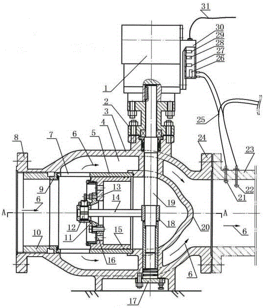
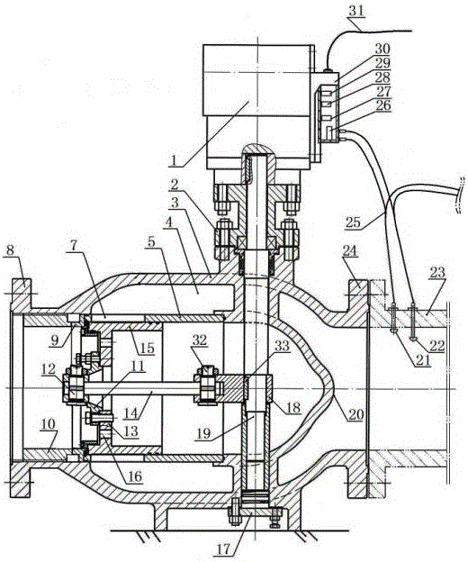
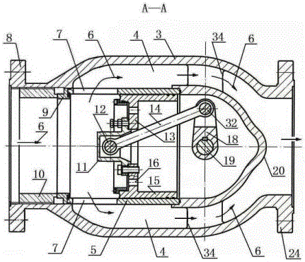
[0024]An axial flow regulating valve proposed by the present invention is mainly composed of a valve body 3, a support seat 2 installed on the valve body 3, an electric head 1, a locking coil 10 fitted in the valve body 3, a valve seat 9. The regulating valve sleeve 5, the valve core 15, the pull rod 14, the regulating rotating shaft 19, the pressure sensor 21 and the flow sensor 22 installed in the output pipe 23 behind the valve are formed. In the valve body 3, a streamlined inner cone head 20 is supported and connected by a group of integrally cast supporting ribs 34, and the valve body 3 and the streamlined inner cone head 20 set in the valve body 3 and the two ends of the valve body 3 are set The inlet flange 8 and the outlet flange 24 are integral structures made of one-time casting. The adjusting shaft 19 vertically passes through the streamlined inn...


PUM


Abstract

The invention discloses an axial-flow type adjusting valve which mainly comprises a valve body, an electric head, an adjusting controller, a connecting rod crank arm mechanism, a pressure sensor and a flow sensor, wherein the electric head is mounted in the valve body, the connecting rod crank arm mechanism is assembled in the valve body, and the pressure sensor and the flow sensor are mounted on an output tube. Output pressure and flow fluctuation signals are acquired on line by electronic integration technology and inputted to the adjusting controller for calculation, adjusting instructions are transmitted to the electric head, the electric head drives an adjusting rotation shaft to rotate, a valve spool is pushed by the connecting rod crank arm mechanism, opening of an adjusting valve port is changed to adjust output flow and pressure, and the output flow and the output pressure can be automatically adjusted and tend to be stable. The axial-flow type adjusting valve has the outstanding advantages of simple structure, convenience in mounting and using, high adjusting precision, high reaction speed, running safety and reliability, high automated control level and good conveying medium stability, and is particularly suitable for being mounted and used on a pipeline requiring high conveying medium dynamic stability.

Description

technical field [0001] The invention relates to an axial-flow regulating valve, which belongs to the technical field of automatic control equipment for transmission and distribution pipe network systems, and is particularly suitable for installation and use on pipelines with high requirements on the dynamic stability of the transmission medium in the petrochemical industry. Background technique [0002] We know that the current control valve products are divided into internal flow channel structure, there are conventional control valves with "S" shaped flow channels in the valve body cavity and axial flow control valves coaxial with the pipeline axis. Objectively speaking, conventional control valves have the advantages of simple structure and low manufacturing cost, and are widely used. However, because the displacement direction of the spool of conventional control valves is perpendicular to the pipeline axis and the medium flows along an "S" shape in the valve body Road m...

Claims


Application Information

Patent Timeline
Patent Type & Authority Applications(China)
IPC IPC(8): F16K31/04F16K31/52F16K3/24F16K3/30F16K17/20
CPCF16K31/04F16K3/246F16K3/30F16K17/20F16K31/046F16K31/523
Inventor 彭国军周斌
Owner SICHUAN ZHONGYOU LEYI ENERGY EQUIP MFG CO LTD
Why Eureka
Try Eureka