Array substrate, array substrate manufacture method and liquid crystal display panel

A technology of array substrate and substrate substrate, applied in nonlinear optics, instruments, optics, etc., can solve the problems of light leakage and poor picture display quality, and achieve the effect of improving the shading rate

Active Publication Date: 2017-01-11
TCL CHINA STAR OPTOELECTRONICS TECH CO LTD
View PDF10 Cites 5 Cited by
  • Summary
  • Abstract
  • Description
  • Claims
  • Application Information

AI Technical Summary

Problems solved by technology

[0008] Embodiments of the present invention provide an array substrate, a manufacturing method of the array substrate, and a liquid crystal display panel that have a relatively high shading rate of the black matrix in the non-display area and that are

Method used


Image

  • Array substrate, array substrate manufacture method and liquid crystal display panel
  • Array substrate, array substrate manufacture method and liquid crystal display panel
  • Array substrate, array substrate manufacture method and liquid crystal display panel

Examples


Embodiment Construction

[0042] The following descriptions of the various embodiments refer to the accompanying drawings to illustrate specific embodiments in which the present invention can be practiced. The directional terms mentioned in the present invention, such as "up", "down", "front", "back", "left", "right", "inside", "outside", "side", etc., are for reference only The orientation of the attached schema. Therefore, the directional terms used are used to illustrate and understand the present invention, but not to limit the present invention.

[0043] In the figures, structurally similar units are denoted by the same reference numerals.

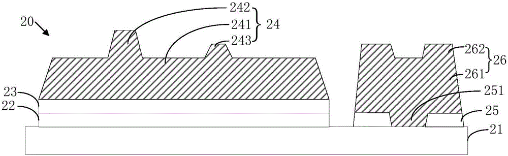
[0044] Please refer to figure 2 , figure 2 It is a schematic structural diagram of a preferred embodiment of the array substrate of the present invention. The array substrate 20 of this preferred embodiment includes a base substrate 21 , a color resist 22 , a first polymer layer 23 , a first black matrix spacer 24 , a second polymer layer 25 and a second...


PUM


Abstract

The invention provides an array substrate which comprises a substrate, a color resistor, a first polymer layer, a first black matrix liner, a second polymer layer and a second black matrix liner, wherein the color resistor is arranged on a display area of the substrate, the first polymer layer is arranged on the color resistor, the first black matrix liner is arranged on the display area of the substrate and comprises a first black matrix and a first liner, and the second polymer layer is arranged on a non-display area of the substrate and comprises at least one groove area. A second color resistor is arranged on part of the non-display area of the substrate, and the second black matrix liner is arranged on the non-display area of the substrate and comprises a second black matrix and a second liner. The invention further provides a liquid crystal display panel and an array substrate manufacture method.

Description

technical field [0001] The invention relates to the field of manufacturing liquid crystal panels, in particular to an array substrate, a method for manufacturing the array substrate, and a liquid crystal display panel. Background technique [0002] With the development of liquid crystal display technology, people have higher and higher requirements for liquid crystal display panels, such as high-brightness liquid crystal display panels or high-resolution liquid crystal display panel lamps. [0003] In order to improve the brightness of the liquid crystal display panel, the best way is to increase the aperture ratio of the liquid crystal display panel. Therefore, the existing liquid crystal display panel adopts a BPS (Black Photo Spacer) technology to manufacture the array substrate, that is, a BPS process is used to replace the original BM (Black Matrix) process and PS (Photo Spacer) process. [0004] For details, please refer to figure 1 , figure 1 It is a structural sch...

Claims


Application Information

Patent Timeline
IPC IPC(8): G02F1/1335
Inventor 叶成亮
Owner TCL CHINA STAR OPTOELECTRONICS TECH CO LTD
Why Eureka
Try Eureka