Formation method and HDPCVD method for metal interlay dielectric film layer

A technology of dielectric film layer and metal layer, applied in the field of semiconductor technology, can solve the problems of abnormal integrated circuit parameters, changing the shape of metal strips of metal layers, chamfering of metal strips, etc.

Inactive Publication Date: 2017-01-11
CSMC TECH FAB2 CO LTD
View PDF4 Cites 4 Cited by
  • Summary
  • Abstract
  • Description
  • Claims
  • Application Information

AI Technical Summary

Problems solved by technology

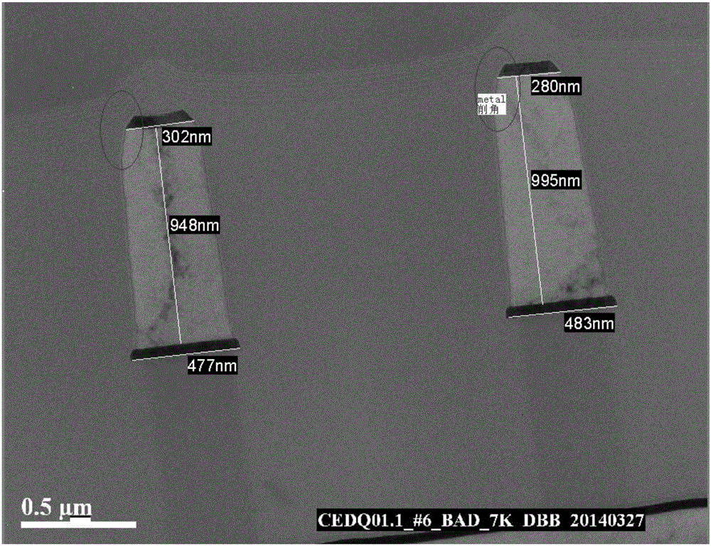
[0003] However, the inventors found that the bombardment with higher power has the risk of changing the shape of the metal strips of the metal layer, especially for metal strips with a high aspect ratio, the impact will be more obvious
like

Method used


Image

  • Formation method and HDPCVD method for metal interlay dielectric film layer
  • Formation method and HDPCVD method for metal interlay dielectric film layer
  • Formation method and HDPCVD method for metal interlay dielectric film layer

Examples


Embodiment Construction

[0022] In order to facilitate the understanding of the present invention, the present invention will be described more fully below with reference to the associated drawings. A preferred embodiment of the invention is shown in the drawings. However, the present invention can be embodied in many different forms and is not limited to the embodiments described herein. Rather, these embodiments are provided so that the disclosure of the present invention will be thorough and complete.

[0023] Unless otherwise defined, all technical and scientific terms used herein have the same meaning as commonly understood by one of ordinary skill in the technical field of the invention. The terms used herein in the description of the present invention are for the purpose of describing specific embodiments only, and are not intended to limit the present invention. As used herein, the term "and / or" includes any and all combinations of one or more of the associated listed items.

[0024] To ana...


PUM


Abstract

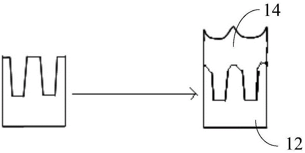
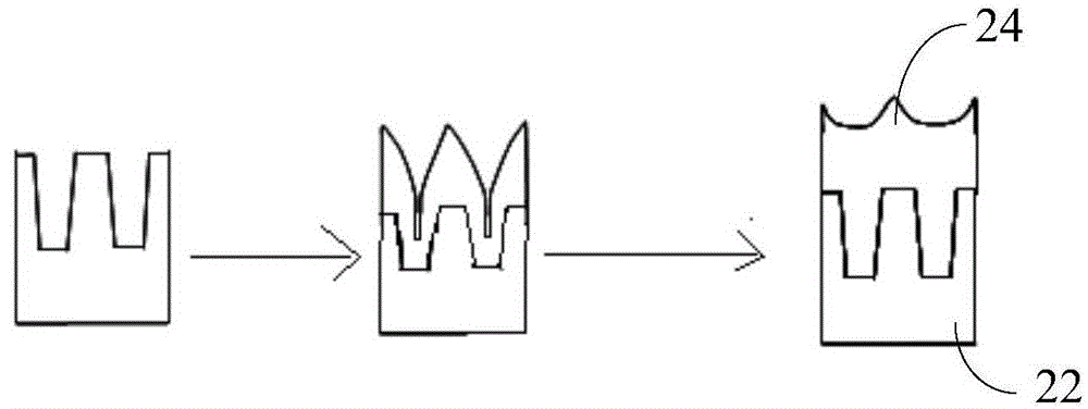
The invention relates to a formation method and an HDPCVD method for a metal interlay dielectric film layer. The HDPCVD method for the metal interlay dielectric film layer adopts a two-step deposition process; a deposition sputtering ratio D/S in the first-step deposition is smaller than the D/S in the second-step deposition; in the first-step deposition, the D/S is 2.1-3.5; the power is 2,800-3,200W; the gas flow is as follows: 100-120sccm of argon, 80-100sccm of oxygen, and 40-50sccm of SiH<4> and SiF<4> altogether; in the second-step deposition, the D/S is 5.1-7.5; the power is 2,300-2,700W; and the gas flow is as follows: 100-120sccm of argon, 160-190sccm of oxygen, and 80-90sccm of SiH<4> and SiF<4> altogether. The HDPCVD method adopts the two-step deposition process; the second-step deposition adopts relatively low power; meanwhile, the gas flow is regulated to enable the environment of an overall deposition chamber to change, thereby obviously relieving a metal angle-cutting phenomenon; meanwhile, relatively low RF power is adopted in the second-step deposition to reduce a bombardment effect, so that the deposition rate in the second-step deposition is increased, thereby improving filling rate while lowering HDP cost; and in addition, the tape-out time of a product can be obviously shortened while the capacity can be improved.

Description

technical field [0001] The invention relates to a semiconductor process, in particular to a high-density plasma chemical vapor deposition method for an inter-metal dielectric film and a method for forming an inter-metal dielectric film. Background technique [0002] In the preparation of traditional high-density plasma chemical vapor deposition of fluorine-doped silicon glass (IMD layer HDPFSG) for micro-sized integrated circuit inter-metal dielectric film layers, the main deposition steps of the HDPFSG menu (recipe) are continuous use of larger High power bombardment (ie sputter) to achieve good filling of fluorine-doped silica glass. [0003] However, the inventors found that bombardment with higher power has the risk of changing the morphology of the metal strips of the metal layer, especially for metal strips with a high aspect ratio, the impact will be more obvious. like figure 1 As shown, there is a phenomenon that the upper end of the metal strip is chamfered, and t...

Claims


Application Information

Patent Timeline
IPC IPC(8): H01L21/768
CPCH01L21/76801H01L2221/1005
Inventor 柳露林于超谭国志
Owner CSMC TECH FAB2 CO LTD
Why Eureka
Try Eureka