Cooling system of hydrogen energy tramcar fuel cell

A fuel cell and cooling system technology, applied in fuel cells, fuel cell additives, fuel cell heat exchange, etc., can solve the problems of high heat dissipation demand, high rated power of hydrogen fuel cells, low working efficiency of hydrogen energy cells, etc. The effect of ensuring the cooling effect and improving the reaction efficiency

Active Publication Date: 2017-01-11
CRRC QINGDAO SIFANG CO LTD
View PDF3 Cites 17 Cited by
  • Summary
  • Abstract
  • Description
  • Claims
  • Application Information

AI Technical Summary

Problems solved by technology

[0003] Due to the limited space under the low-floor tram car, most of the equipment is installed on the roof platform, and the low-floor tram powered by hydrogen energy needs to add hydrogen fuel cells, cooling devices, hydrogen storage devices, DC-DC, traction battery and other hydrogen power system equipment, while the hydrogen fuel cell has a large rated power and high heat dissipation requirements, so the cooling system needs to meet the high-power heat dissipation requirements of the hydrogen fuel cell in the limited space on the roof; the hydrogen fuel cell reaction exchange membrane The reaction efficiency is the highest at around 60°C, but when the ambient temperature is too low or the hydrogen fuel cell has just started, the temperature of the coolant in the cooling system is too low, and the hydrogen fuel cell cannot be at the optimal reaction ambient temperature, resulting in the hydrogen energy cell working Low efficiency; at the same time, because the ion concentration of the cooling liquid of the hydrogen fuel cell cooling system is too high, it will greatly affect the service life of the hydrogen fuel cell reaction exchange membrane, so a reasonable cooling system is required to ensure that the hydrogen energy cell works in a constant temperature reaction environment

Method used


Image

  • Cooling system of hydrogen energy tramcar fuel cell

Examples


Embodiment Construction

[0031] In order to make the above objects, features and advantages of the present invention more comprehensible, the present invention will be further described in detail below in conjunction with the accompanying drawings and specific embodiments.

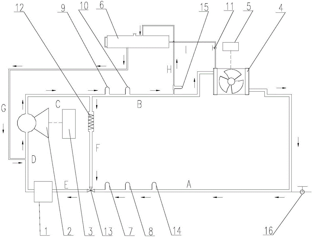
[0032] Such as figure 1 As shown, the present invention provides a cooling system for a hydrogen energy tram fuel cell, including a cooling cycle formed by sequentially connecting the hydrogen fuel cell 1, a circulation device and a cooling device through pipelines;

[0033] The cooling system also includes an electric heating tube 12, the electric heating tube 12 communicates with the circulation device through a pipeline at one end, and communicates with the hydrogen fuel cell 1 through a pipeline at the other end, forming a heating circulation loop.

[0034] Specifically, the hydrogen fuel cell 1 in this embodiment generates electric energy, and hydrogen and oxygen in the air react to generate electricity and water under the ac...


PUM


Abstract

The invention discloses a cooling system of a hydrogen energy tramcar fuel cell. The cooling system comprises a hydrogen fuel cell, a circulating device, a cooling device and an electric heating pipe, wherein the hydrogen fuel cell, the circulating device and the cooling device are sequentially connected to form a cooling circulating loop; one end of the electric heating pipe I communicates with the circulating device through a pipeline, the other end communicates with the hydrogen fuel cell through a pipeline, and a heating circulating loop is formed. The temperature of a coolant entering the hydrogen fuel cell can be controlled within the best reaction temperature range accurately and more stably, so that the hydrogen fuel cell is located in a proper reaction temperature environment, and the reaction efficiency of the hydrogen fuel cell is improved; the cooling system is simple in structure, has an obvious effect and saves energy.

Description

technical field [0001] The invention relates to the field of trams, in particular to a cooling system for fuel cells of hydrogen energy trams. Background technique [0002] A fuel cell is a power generation device that directly converts the chemical energy present in fuel and oxidant into electrical energy. It is a new type of power generation device with high efficiency and environmental protection, and is widely used in various fields. A hydrogen fuel cell is a battery that uses the chemical element hydrogen to manufacture energy storage. Since only water is produced in the reaction of a hydrogen fuel cell, it is a green and environmentally friendly energy source. [0003] Due to the limited space under the low-floor tram car, most of the equipment is installed on the roof platform, and the low-floor tram powered by hydrogen energy needs to add hydrogen fuel cells, cooling devices, hydrogen storage devices, Hydrogen power system equipment such as DC-DC and traction batter...

Claims


Application Information

Patent Timeline
Patent Type & Authority Applications(China)
IPC IPC(8): H01M8/04014H01M8/04029H01M8/04007
CPCH01M8/04014H01M8/04029H01M8/04037H01M8/04007Y02E60/50H01M2250/20H01M8/04067
Inventor 胡玉杰高洪镇杨兵牟晓莎任广强刘玉文赵泽娟
Owner CRRC QINGDAO SIFANG CO LTD
Why Eureka
Try Eureka