Switching power supply unit
A switching power supply and switching element technology, applied in emergency protection circuit devices, output power conversion devices, electrical components, etc., can solve problems such as ineffectiveness, poor overcurrent protection function, and unsatisfactory specifications, and achieve cost suppression Effect
- Summary
- Abstract
- Description
- Claims
- Application Information
AI Technical Summary
Problems solved by technology
Method used
Image
Examples
no. 1 Embodiment approach
[0060] Figure 4 It is a diagram of a switching power supply device 1A according to the first embodiment of the present invention.
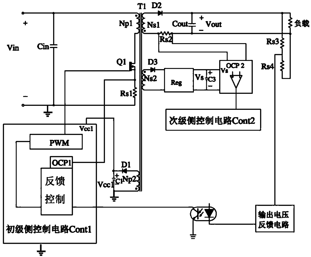
[0061] Figure 4 The switching power supply device 1A shown is the converter power supply mode and the background technology mentioned image 3 The same power supply device as the flyback type power supply device has: a transformer T1 having a primary coil Np1 and a secondary coil Ns1 opposite in polarity to the primary coil Np1; a switching element Q1 connected in series to the primary coil Np1; a switching power supply device The output of 1A is a constant voltage control circuit Cont3 that controls the switching operation of the switching element Q1; and the auxiliary coil Np2 wound with the same polarity as the secondary coil Ns2. The voltage generated by the first rectifier element D1 and the capacitor C1 connected in series with the auxiliary coil Np2 in the direction of supplying power when the switching element is turned off is referred...
no. 2 Embodiment approach
[0079] Figure 7 It is a figure of the switching power supply apparatus 1B of 2nd Embodiment of this invention. The difference between the switching power supply device 1B of the second embodiment and the switching power supply device 1A of the first embodiment is that a power limiting unit PLT is provided on the secondary side.
[0080] Figure 7The shown switching power supply device 1B of the second embodiment includes: a transformer T1 having a primary coil Np1 and a secondary coil Ns1 having a polarity opposite to that of the primary coil Np1; a switching element Q1 connected in series to the primary coil Np1; The output of device 1B controls the switching operation of the switching element Q1 in a constant voltage manner and performs the primary side control circuit Cont4 for detection of abnormalities such as overcurrent on the primary side and its protection action, and the voltage value of the auxiliary coil on the secondary side The secondary side control circuit C...
no. 3 Embodiment approach
[0084] Figure 8 It is a figure which shows the switching power supply apparatus 1C of 3rd Embodiment of this invention. In the switching power supply device 1C of the third embodiment, the auxiliary winding Ns3 in the switching power supply device 1B of the second embodiment, the fourth rectifying element D4 connected in series to the auxiliary winding Ns3 , and the fourth The capacitor C4 connected to the rectifying element D4 is moved to the primary side. That is, the primary side includes an auxiliary winding Np3, a fifth rectifying element D5 connected in series to the auxiliary winding Np3, and a capacitor C2 connected to the fifth rectifying element D5. The primary-side control circuit Cont3 of the switching power supply device 1C of the third embodiment includes a voltage control function, an overcurrent protection unit OCP, and a power limiting unit PLT. The power limiting unit PLT monitors the voltage Vcc3 of the capacitor C2, and controls the switching element Q1 ...
PUM
 Abstract
Description
Claims
Application Information
 - R&D
- Intellectual Property
- Life Sciences
- Materials
- Tech Scout
- Unparalleled Data Quality
- Higher Quality Content
- 60% Fewer Hallucinations
Browse by: Latest US Patents, China's latest patents, Technical Efficacy Thesaurus, Application Domain, Technology Topic, Popular Technical Reports.
© 2025 PatSnap. All rights reserved.Legal|Privacy policy|Modern Slavery Act Transparency Statement|Sitemap|About US| Contact US: help@patsnap.com


