Phase inversion method based on focal length fixed Fresnel zone plate

A phase inversion and focal length technology, applied in the field of wavefront sensing, can solve the problems of increased structural complexity and reduced reliability of optical realization

Active Publication Date: 2017-01-18
INST OF OPTICS & ELECTRONICS - CHINESE ACAD OF SCI
View PDF11 Cites 12 Cited by
  • Summary
  • Abstract
  • Description
  • Claims
  • Application Information

AI Technical Summary

Problems solved by technology

However, acquiring multiple frames of far-field images at the same time means increasi

Method used


Image

  • Phase inversion method based on focal length fixed Fresnel zone plate
  • Phase inversion method based on focal length fixed Fresnel zone plate
  • Phase inversion method based on focal length fixed Fresnel zone plate

Examples


Embodiment

[0034] In an exemplary embodiment of the present invention, a phase inversion method based on a mixed focal length Fresnel zone plate is provided. The present invention will be further described below in conjunction with the accompanying drawings and embodiments.

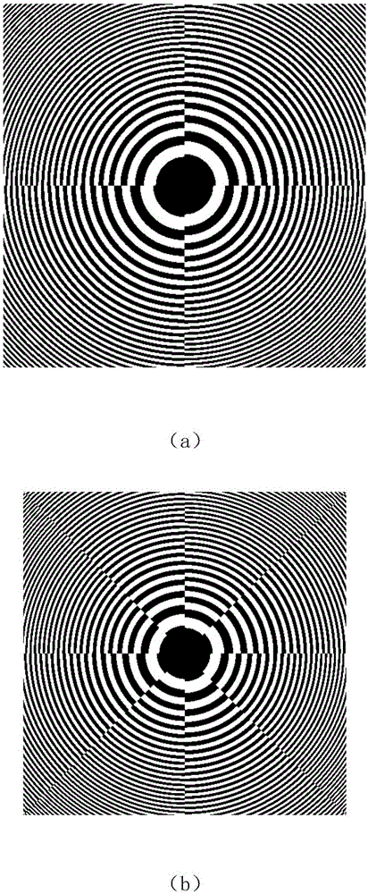
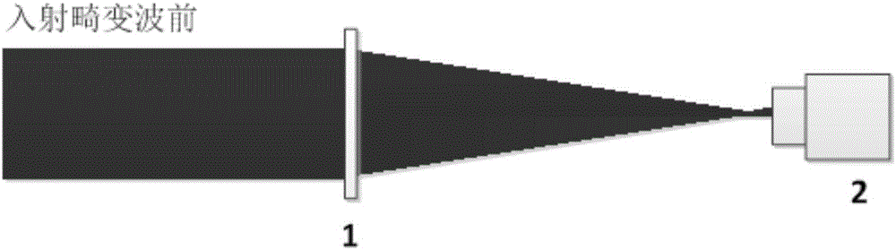
[0035] figure 1 (a) shows a schematic diagram of a Fresnel lens. In this example, it is divided into four parts. The design focal lengths of the 1st and 3rd quadrants are 1200mm, and the design focal lengths of the 2nd and 4th quadrants are 1000mm (multiple focal lengths are also possible). image 3 It is a system optical path diagram, and the incident light wave front phase to be measured is a random wave front (PV=3.1852rad, rms=0.6452rad) composed of a 65th order Zernike polynomial in the embodiment, as Figure 5 (a) shown. The far-field light intensity distribution through the Fresnel zone plate is as follows: Figure 4 (a) shown.

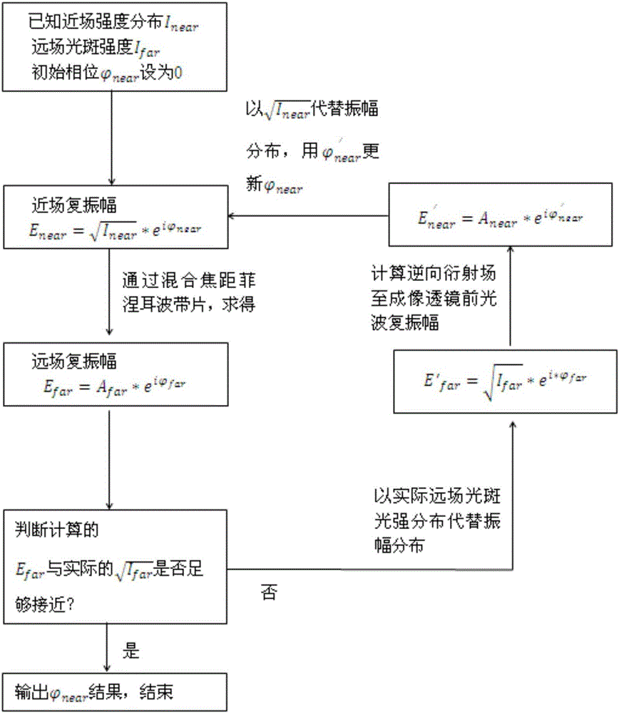
[0036] Step 1: The near-field intensity distribution I of the incident beam ...


PUM


Abstract

The invention provides a phase inversion method based on a focal length fixed Fresnel zone plate. Part of focal plane and de-focal plane information of wavefront can be collected at the same time at the same position in the far field, only one frame of image is needed, the method based on the Fresnel zone plate is simple in components and is portable, accurate phase inversion can be realized on the basis of the single-frame far-field image, and the calculating speed and the precision are high.

Description

technical field [0001] The invention relates to a phase inversion method based on a mixed focal length Fresnel zone plate, belonging to the technical field of wavefront sensing. Background technique [0002] Phase inversion technology is an important branch of wavefront sensing technology, which is characterized by directly using the collected far-field spot image information of the beam, and inverting and calculating the near-field wavefront phase distribution information of the beam through the theory of diffraction optics. According to the far-field information input conditions, the phase inversion technology can be divided into the classic phase inversion technology based on a single frame image and the phase inversion technology based on a multi-frame image. The phase inversion technology of single-frame image mainly includes GS algorithm, YG algorithm, etc.; the phase inversion technology of multi-frame image mainly includes curvature wavefront sensing technology, phas...

Claims


Application Information

Patent Timeline
IPC IPC(8): G02B26/06G01J9/00
CPCG01J9/00G01J2009/002G02B26/06
Inventor 孔庆峰王帅杨平于信杨康建赖柏衡林海奇董理治汤国贸许冰
Owner INST OF OPTICS & ELECTRONICS - CHINESE ACAD OF SCI
Why Eureka
Try Eureka