
Automatic membrane connecting device

A film device and automatic technology, applied in the direction of packaging material feeding device, packaging, transportation and packaging, etc., can solve the problems of low work efficiency, unsightly appearance, increased labor intensity, etc., and achieve high work efficiency, good film quality, high quality work

Inactive Publication Date: 2017-01-25
TIANJIN KAIFENGYI TECH CO LTD
View PDF5 Cites 2 Cited by
  • Summary
  • Abstract
  • Description
  • Claims
  • Application Information

AI Technical Summary

Problems solved by technology

[0002] At present, when the domestic packaging machine is continuously running at high speed in the supporting production line, after the first roll of film is used up, it is generally necessary to stop to pick up the second roll of film. Under normal circumstances, the operator needs to stop for 1-3 minutes to complete the film splicing process. When the front-end production line cannot be shut down due to continuous production, the shutdown of the packaging machine will cause dozens of products to pile up. When the packaging machine connects the film, the color marks will not be aligned correctly, and there will often be situations where more than a dozen packages of color marks will not be cut correctly, resulting in material loss. Waste, waste of manpower, low work efficiency
[0003] In addition, there will be a large section of overlapping parts after the film is attached, which is generally cut off during post-processing, which undoubtedly increases the labor intensity, which will also affect the follow-up process and use, and it is not beautiful, so there is a It is necessary to design an automatic film splicing device, which can realize automatic film splicing without stopping the machine, and the overlapping part is small, without affecting the appearance and use

Method used


Image

  • Automatic membrane connecting device

Examples


Embodiment Construction

[0020] It should be noted that, in the case of no conflict, the embodiments of the present invention and the features in the embodiments can be combined with each other.

[0021] In describing the present invention, it should be understood that the terms "center", "longitudinal", "transverse", "upper", "lower", "front", "rear", "left", "right", " The orientations or positional relationships indicated by "vertical", "horizontal", "top", "bottom", "inner" and "outer" are based on the orientations or positional relationships shown in the drawings, and are only for the convenience of describing the present invention and Simplified descriptions, rather than indicating or implying that the device or element referred to must have a particular orientation, be constructed and operate in a particular orientation, and thus should not be construed as limiting the invention. In addition, the terms "first", "second", etc. are used for descriptive purposes only, and should not be understood ...


PUM

PropertyMeasurementUnit
widthaaaaaaaaaa

Abstract

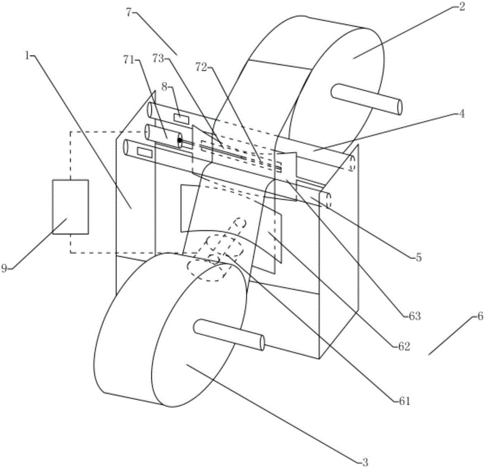
The invention provides an automatic film splicing device, comprising a frame, a working film roll, a standby film roll, a first film guide roll, a second film guide roll, a film splicing mechanism and a film cutting mechanism, a working film roll and a standby film roll The film rolls are respectively arranged on both sides of the frame, and the first film guide roller and the second film guide roller are arranged in parallel at the upper end of the frame at the entrance of the film, and are set close to one side of the working film roll and the standby film roll respectively. No film detection sensor is provided on the first film guiding roller, the film splicing mechanism includes a first driving member, a first film pressing plate and a second film pressing plate, and the film cutting mechanism includes a second driving member, a cutting tool and a film cutting channel , also includes a controller for controlling the operation of the first driving member and the second driving member, and the controller is electrically connected with the membrane-free detection sensor. The invention can realize fast film splicing, non-stop film splicing, good film splicing quality, fast speed, and high working quality; the setting of the film cutting mechanism can automatically cut the superimposed parts after splicing the film, and the working efficiency is high without affecting the follow-up process carried out.

Description

technical field [0001] The invention belongs to the field of mechanical equipment, and in particular relates to an automatic film splicing device. Background technique [0002] At present, when the domestic packaging machine is continuously running at high speed in the supporting production line, after the first roll of film is used up, it is generally necessary to stop to pick up the second roll of film. Under normal circumstances, the operator needs to stop for 1-3 minutes to complete the film splicing process. When the front-end production line cannot be shut down due to continuous production, the shutdown of the packaging machine will cause dozens of products to pile up. When the packaging machine connects the film, the color marks will not be aligned correctly, and there will often be situations where more than a dozen packages of color marks will not be cut correctly, resulting in material loss. Waste, also wasted manpower, work efficiency is low. [0003] In addition...

Claims


Application Information

Patent Timeline
Patent Type & Authority Applications(China)
IPC IPC(8): B65H19/18B65B41/12
CPCB65H19/181B65B41/12B65H2701/176B65H2701/1842B65H2801/81
Inventor 何延凯
Owner TIANJIN KAIFENGYI TECH CO LTD
Learn More