High-speed rail unballasted double-track pavement multifunctional intelligent vehicle

A smart car and multi-functional technology, applied in the field of automation, can solve the problems of low engine power, time-consuming and labor-intensive operation, and confusion on the construction site

Inactive Publication Date: 2017-01-25
胡德令
View PDF2 Cites 14 Cited by
  • Summary
  • Abstract
  • Description
  • Claims
  • Application Information

AI Technical Summary

Problems solved by technology

In short, all the above-mentioned spring fastener machines have low efficiency, few functions, and inconvenient use, and cannot meet the needs of modern high-speed railway construction.
[0003] In the railway tracks that have been put into operation, these "clip fastening machines" are only used for maintenance and inspection, and each bolt is tightened with more than 100 cattle. Torque, the engine power is small, the working speed is very slow, the operation is time-consuming and laborious, and the nut sleeve needs to be touched with the foot to find the position, so the work efficiency is very low; and because there is no torque sensor, the tightening torque is unknown and there is no data indication refer to
[0004] For the laying of CRTSⅢ ballastless track for new railways, cement sleeper paving for high-speed railways is set as the standard. The implementation of the current process requires that the spikes have to be tightened and disassembled many times to complete. At present, due to the intersection of various types of work in the industry, the process formulation is repeated. Whether the rail stud nuts are tightened, regardless of the gauge, whether the tightening torque is within the standard tolerance requirements? Or is there any change in gauge rebound after the spike nut is tightened? Can only the full-time gauge testing personnel find out that the gauge standard size is out of tolerance? Remedial work is done later. This kind of process regulation is different, repetitive labor, time-consuming and labor-intensive. The reason is that there is no special equipment for the gauge correction to lock at the standard distance when the spring bolts are automatically tightened.
[0005]At present, the ballastless cement sleepers of my country Railway Bureau are all standardized in factories. After being transported to the construction site, installed and adjusted, the rails are put into the sleeper grooves, and then the spring bars are manually pushed into the working position, then the rails are pressed, and then the clip fastener bolts are tightened. This installation process increases the labor intensity of the workers and prolongs the construction period. Time, such a construction method is laborious and time-consuming
[0006] After investigating the systems of China Railway Bureaus, the industry and patents, the current high-speed rail system track fasteners, spikes and nuts are randomly tested for tightening torque. The data is not entered, and multiple types of work are artificially divided. , one may cause damage to the threads of bolts and nuts, affecting driving safety; the other is that this artificial division causes the extension of the construction period and confusion on the construction site, so it is necessary to produce a gauge automatic locking, automatic walking stepping, elastic The special equipment for automatic assembly and disassembly of bolts was born to serve the construction of modern high-speed rail

Method used


Image

  • High-speed rail unballasted double-track pavement multifunctional intelligent vehicle
  • High-speed rail unballasted double-track pavement multifunctional intelligent vehicle
  • High-speed rail unballasted double-track pavement multifunctional intelligent vehicle

Examples


Embodiment approach 1

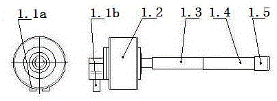
[0026] Depend on figure 1 As shown in: the present invention implements the structure of "automatic tightening and dismounting device for four elastic fasteners": the features include oil inlet joint (1.1a), oil outlet joint (1.1b), hydraulic motor (1.2), torque pressure sensor (1.3 ), a telescopic oil cylinder (1.4), and a sleeve wrench (1.5); there is a through hole in the middle of the hydraulic motor (1.2), and a torque and pressure sensor (1.3) and a telescopic oil cylinder (1.4) are installed in the middle of the through hole. Bolt sleeve wrench (1.5) is installed at the lower end of the telescopic oil cylinder (1.4), and they are connected end to end to form a "spring bolt tightening and dismounting device";

[0027] After starting up: the program controller outputs two commands successively to open the respective hydraulic valves, one is to fill oil to the lower nozzle of the telescopic cylinder (1.4), and the other is to fill oil to the forward rotation nozzle of the...

Embodiment approach 2

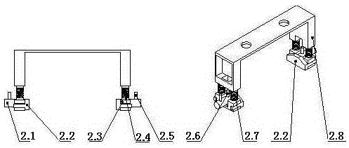
[0030] Depend on figure 2 As shown in the figure: the present invention installs the structure of "four spring fasteners pushing in place device" inside and outside the two rails at the front end of the smart car. The device will automatically push the four spring fasteners on the ballastless concrete sleeper to the pressure The design position of the tight rail, wherein the device consists of a cylinder (2.1), a push block (2.2), a cylinder support (2.3), a shaft (2.4), a forward oil port (2.5), a backward oil port (2.6), a spring (2.7 ), body (2.8) composition;

[0031] Elastic strip push upper device installs oil cylinder (2.1), push block (2.2), shaft (2.4) and spring (2.7) on the oil cylinder support (2.3) to form a single body, and then install the four single bodies on the two bodies (2.8) constitutes a "four-bar push-up device";

[0032] Its working principle is: when the "four elastic strips push the upper position device" moves to the pre-positioned position of th...

Embodiment approach 3

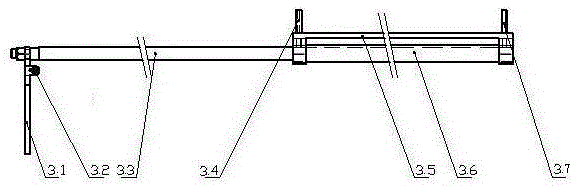
[0034] Depend on image 3 Shown in: the present invention implements and installs "smart car automatic stepping device" in the two rails below the smart car chassis, and the work of this device makes the smart car automatically step forward according to the program; Ratchet mechanism (3.2), oil cylinder shaft (3.3), oil inlet (3.4), mounting base (3.5), stepping oil cylinder (3.6), oil outlet (3.7);

[0035] When the "automatic stepping device" works, the program controller instructs to open the A hydraulic valve, and the A hydraulic valve fills the oil inlet (3.7) of the stepping oil cylinder (3.6), so that the oil cylinder shaft (3.3) is stretched out, and the oil cylinder shaft ( 3.3) It drives the ratchet wheel mechanism (3.2) and soles of the feet (3.1), and waits for the order after stretching out a set distance; when the bolts are tightened and the gauge locking device is finished, the system sends an instruction to open B hydraulic valve, B hydraulic valve fills the o...


PUM


Abstract

The invention provides a high-speed rail unballasted double-track pavement multifunctional intelligent vehicle, and relates to the technical field of high-speed rail underground railway track pavement gauge positioning, spike screwing and stepping automation. A system comprises four elastic strip buckle automatic push-in-place device, an intelligent vehicle automatic stepping device, a standard gauge positioning, rectifying and locking device, an intelligent vehicle up and down rail device, a measuring, analyzing, recording and networking device and an intelligent vehicle central processing and decision making module. Spot testing is conducted on tightening torque of current high-speed rail system rail buckle elastic strip spike nut, data is not recorded in, artificial cutting is conducted by various work types, detaching and assembling are repeated multiple times, bolts, nuts and threads are damaged, and driving safety is influenced; due to artificial cutting, the construction period is prolonged, the construction site is disordered, and the multifunctional intelligent vehicle is created. The technical problem that in pavement, the multiple procedures of screwing, detaching and gauge detecting are combined is solved, the rail pavement engineering quality is ensured, production efficiency is improved, the engineering construction period is shortened, and the labor intensity of operators is relieved.

Description

technical field [0001] The invention relates to a method of automatically adjusting and controlling the gauge to be locked within the tolerance of the standard gauge, automatically pushing the four elastic strips from the initial state to the pressing position of the two rails, and automatically completing the tightening of the four elastic strip spikes according to the specified torque. The automatic step-by-step positioning of smart cars, the data cloud library device for Internet + data recording and analysis, and the multifunctional smart car solution of the present invention belong to the field of automation technology. Background technique [0002] After countries around the world entered high-speed railways, ballastless concrete sleepers replaced wooden sleepers, and all countries adopted the method of elastic spike bolts to compress the rails. At the beginning, a long-handled wrench was used to manually rotate back and forth to tighten the spike nuts, and the tighteni...

Claims


Application Information

Patent Timeline
Patent Type & Authority Applications(China)
IPC IPC(8): E01B29/24
Inventor 李心怡
Owner 胡德令
Why Eureka
Try Eureka