
A steel trestle bridge in deep water, high flow rate, exposed high-strength steep rock sea area and its construction method

A high-flow, high-strength technology, used in bridges, bridge construction, bridge parts, etc., can solve the problems of difficult construction, deformation and collapse of trestle, and short construction period, and avoid deformation and collapse of trestle, increase construction speed, and construction period. short effect

Active Publication Date: 2019-06-07
CCCC SECOND HARBOR ENG
View PDF6 Cites 2 Cited by
  • Summary
  • Abstract
  • Description
  • Claims
  • Application Information

AI Technical Summary

Problems solved by technology

[0004] For the artificial overburden plan, a large number of soil bags need to be thrown and filled within the range of the steel pipe piles of the steel trestle bridge. The soil bags are easy to roll down or be washed away by the water flow, resulting in a large waste. This project requires a large amount of engineering, long construction period and high cost
[0005] For the jacket scheme, it is necessary to connect multiple steel pipe piles whose bottom matches the seabed topography according to their relative positions on land or on board to form a jacket. The large-scale transport ship transports it to the trestle pile position, and the large-tonnage crane ship lifts and installs it. , and set an underwater cofferdam at the bottom of the jacket, and pour underwater concrete. This scheme has a large amount of engineering, difficult construction, long period and high cost
[0006] For the first anchoring scheme of cast-in-situ piles, the above-water platform is used to locate the steel pipe piles of the steel trestle bridge, the guide frame is lowered to lower the steel pipe piles to the rock surface, the drilling rig forms holes in the steel pipe piles, and the anchor piles are constructed to anchor them in the rock formation. Then carry out the construction of the upper structure of the steel trestle bridge. During the construction of the cast-in-place piles, the bottom of the steel pipe piles is prone to grout leakage, and the construction period is long and the cost is high.
[0007] For the post-anchoring scheme of cast-in-situ piles, a group of steel pipe piles is quickly inserted and driven by a piling ship, and the adjacent steel pipe piles are connected into a whole. Build the Bailey beam on top of the bridge, and then build the bridge deck, and then use the drilling rig on the bridge deck to carry out the anchor pile construction of the steel pipe pile. The pipe pile is driven into the rock surface to a sufficient depth. The bottom opening of the steel pipe pile is easily curled during the driving process, and a single steel pipe pile is easy to shake and fall under the action of a large flow rate after being inserted. During the construction of the cast-in-place pile, the steel pipe pile The bottom opening is easy to leak grout. During the punching process, the rock face at the bottom of the pile is easy to sink due to the collapse of the trestle due to the collapse of the rock surface at the bottom of the pile, which leads to a large safety risk. It is difficult to correspond to the main node of the thunder beam, which affects the overall force of the trestle bridge, and also increases the amount of materials and high cost

Method used


Image

  • A steel trestle bridge in deep water, high flow rate, exposed high-strength steep rock sea area and its construction method
  • A steel trestle bridge in deep water, high flow rate, exposed high-strength steep rock sea area and its construction method
  • A steel trestle bridge in deep water, high flow rate, exposed high-strength steep rock sea area and its construction method

Examples


Embodiment Construction

[0045] pass below Figure 1 to Figure 11 And the way of enumerating some optional embodiments of the present invention, the technical solution of the present invention (including the preferred technical solution) is described in further detail, and any technical feature and any technical solution in this embodiment do not limit the protection scope of the present invention .

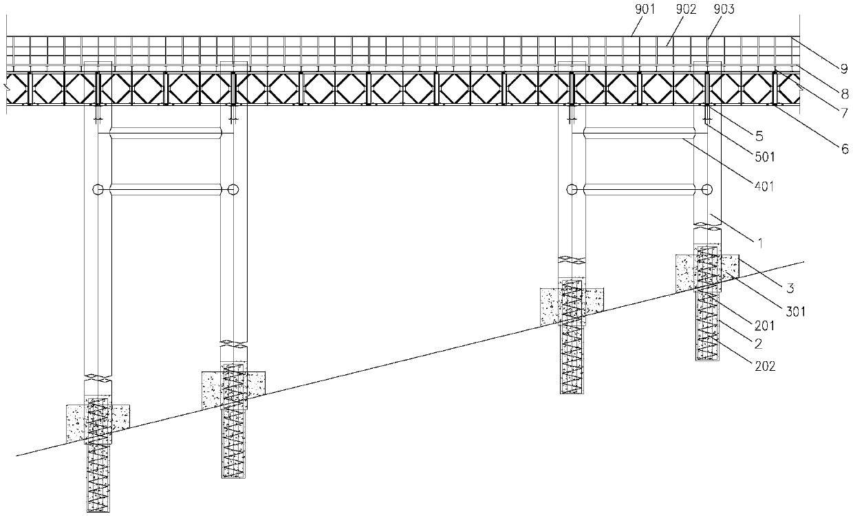
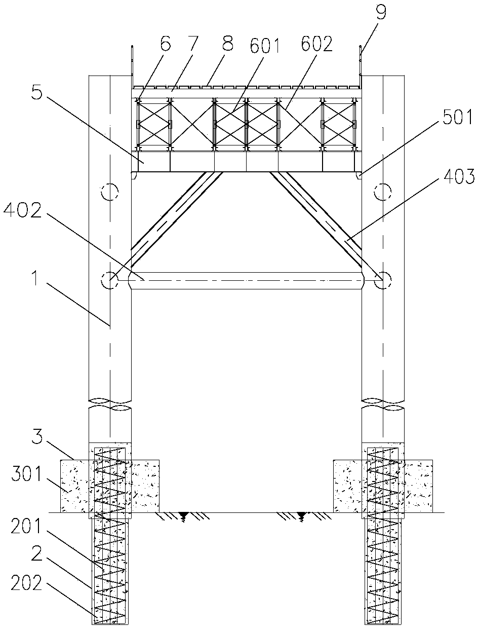
[0046] like figure 1 and figure 2 As shown, this embodiment provides a steel trestle bridge in deep water, high flow rate, exposed high-strength steep rock sea area, including: steel pipe pile 1, cast-in-situ pile 2, steel cofferdam 3, first flat connecting rod 401, second flat connecting rod 402, Diagonal brace 403, load-bearing main beam 5, Bailey beam 6, distribution beam 7, panel 8, railing 9;

[0047] The upper half of the cast-in-place pile 2 is located at the inner bottom of the steel pipe pile 1, and the lower half is located in the bedrock at the bottom of the steel pipe pile 1. The cast-in-...


PUM


Abstract

The invention discloses a deepwater high-flow-rate exposed high-strength steep rock sea area steel trestle and a construction method thereof. Steel pipe piles of a steel trestle foundation are stabilized in the bed rock, the upper part structure of the steel trestle is set up, the steel pipe piles are subjected to rock-socketed anchoring construction, the steel trestle construction speed is improved greatly, a series of conventional problems affecting the progress, the quality and the safety during the steel trestle construction are solved, a positioning ship and a pile driving barge are used for stabilizing the piles so that toppling caused due to deviation and shaking under high-flow-rate operation due to the defect that the into-rock depth of the steel pipe piles is not enough is avoided, bottom elevation self-adaption steel cofferdam pouring underwater concrete is put under the outer sides of the steel pipe piles so that the friction force of the steel pipe piles and the bed rock is increased, the stability of the steel pipe piles is improved, trestle deformation collapse caused by bottom opening slurry leaking and steel pipe pile sinking when holes are drilled in the steel pipe piles is avoided, bearing girds are welded between the horizontal steel pipe piles so that the phenomenon that structure stress is affected by non-correspondence of Bailey beam major nodes and the bearing beams is avoided, and the purposes that the steel trestle construction period is short, the cost is low and the construction is safe and efficient are realized.

Description

technical field [0001] The invention belongs to the technical field of bridge engineering construction over water, and in particular relates to a steel trestle bridge in deep water, high flow rate, exposed high-strength steep rock sea area and a construction method thereof. Background technique [0002] The traditional steel trestle mostly adopts the structural form of single-row steel pipe piles and Bailey beams, and is mostly used in waters with small water depth, low flow velocity and thick covering layer. When constructing steel pipe piles of this kind of steel trestle, vibratory hammer or The piling hammer is directly driven into the overburden to the design level. [0003] For trestle bridges in exposed steep rock areas, if the traditional method is used for construction, the steel pipe piles cannot be driven into the rock formation to the embedded depth. guarantee, thereby affecting the safety performance of the trestle bridge and the construction progress of the mai...

Claims


Application Information

Patent Timeline
Patent Type & Authority Patents(China)
IPC IPC(8): E02D27/14E02D27/52E02D19/04E02D7/06E01D21/00E01D19/02E01D19/10
CPCE01D19/02E01D19/10E01D21/00E02D7/06E02D19/04E02D27/14E02D27/525E02D2300/002E02D2300/0029
Inventor 徐洲向继华潘文铭唐蔚东曾宪柳
Owner CCCC SECOND HARBOR ENG
Learn More