Online dynamic balance correction method of large-size draught fan impeller

A technology of fan impeller and correction method, applied in static/dynamic balance test, machine/structural component test, measurement device, etc., can solve problems such as wasting time and affecting normal production

Inactive Publication Date: 2017-01-25
PANGANG GRP ENG TECH
View PDF5 Cites 10 Cited by
  • Summary
  • Abstract
  • Description
  • Claims
  • Application Information

AI Technical Summary

Problems solved by technology

In the past, the dynamic balance correction after the repair of the impeller of a large fan was entrusted to the unit with the fan motor balancing machine. normal production

Method used


Image

  • Online dynamic balance correction method of large-size draught fan impeller
  • Online dynamic balance correction method of large-size draught fan impeller
  • Online dynamic balance correction method of large-size draught fan impeller

Examples


Embodiment 1

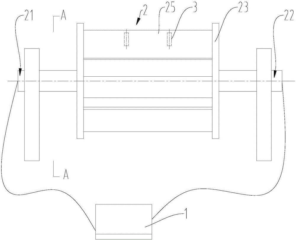
[0031] An ironworks has adopted the above method three times to carry out on-site dynamic balance correction on the impeller of the circulating fan of the CDQ system after repair. Fan model: 25151Z / 1024, fan speed n=1500r / min, fan mass W=7800Kg.

[0032] the first time:

[0033] First of all, the original vibration amplitude and phase of the bearing bush at the driving end 21 and the passive end 22 of the fan impeller are measured with the vibration detection balance instrument 1 on site, as shown in Table 1:

[0034] Table 1 The original vibration amplitude and phase of the fan bearing

[0035]

[0036]

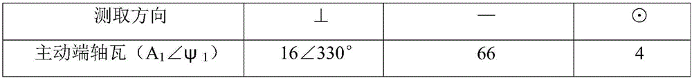
[0037] In Table 1: ⊥ means the vertical direction, — means the horizontal direction, and ⊙ means along the impeller axis.

[0038] It can be seen from Table 1 that the vertical vibration phases of the bearing pad at the active end and the bearing pad at the passive end are basically the same, but the vibration amplitudes are greatly different. It is a typical dynami...

Embodiment 2

[0071] Example 2: A certain ironworks adopted the above method to perform on-line dynamic balance correction on the impeller of the repaired coke screening and dust removal fan. The coke screening fan model: CGR218-73DIF, the conveying medium is coke dust and flue gas; fan speed n=1600r / min, rotor mass W=8100Kg; radius R=1250mm.

[0072] First of all, the original vibration amplitude and phase of the bearing bush at the driving end 21 and the passive end 22 of the fan impeller are measured with the vibration balance instrument 1 on site, as shown in Table 7:

[0073] Table 7 Original vibration amplitude and phase of fan bearing

[0074] Measure direction ⊥ — ⊙ Drive end bearing bush (A 1 ∠ψ 1 )

17∠330° 67 5 Bearing bush at passive end (A 2 ∠ψ 2 )

9∠320° 35 18

[0075] For the impeller of the C-series coke dust removal fan, the mass of the rotor is W=8100Kg; the radius R=1250mm; the speed n=1600r / min; the above parameters are brough...


PUM


Abstract

The invention discloses an online dynamic balance correction method of a large-size draught fan impeller, belonging to the field of equipment overhauling, and aiming at reducing impeller assembling and disassembling procedures and shortening an overhauling period. The online dynamic balance correction method comprises the following steps: A, connecting one end of a vibration detection balancing apparatus with a driving end of the draught fan impeller on line and connecting the other end of the vibration detection balancing apparatus with a driven end of the draught fan impeller; marking a vibration starting phase point on a wheel disc of the impeller; B, starting the vibration detection balancing apparatus and detecting an original vibration amplitude and an original phase of a bearing bush at the driving end of the draught fan impeller; C, calculating balance counter weight needing to be added and a phase of the added balance counter weight; and D, adding the balance counter weight to the back surface of the impeller. According to the online dynamic balance correction method of the large-size draught fan impeller, after the balance counter weight and the mounting position of the balance counter weight are measured in a large-size draught fan installation site by utilizing the vibration detection balancing apparatus, the balance counter weight is mounted on the impeller and the draught fan impeller does not need to be assembled and disassembled, so that the impeller assembling and disassembling procedures are reduced and the overhauling period is shortened.

Description

technical field [0001] The invention belongs to the field of equipment maintenance, in particular to an online dynamic balance correction method for a large fan impeller. Background technique [0002] Large fan refers to a double-pivot centrifugal fan with a ratio of impeller length to impeller diameter of less than 1.5 and a fan speed of less than 7500r / min. Large fan is one of the important production equipment in mining, metallurgy, power generation and other industries. Whether its operation is normal or not is directly related to the smooth operation of the system using large fan. Fans are generally used in environments with high dust content. The working system of the fan is 345 days a year, 24 hours a day continuous work, and such long-term operation, cracks and wear on the fan impeller, once cracks or wear on the fan impeller, the impeller needs to be repaired, and the impeller needs to be dynamically balanced after repair. In the past, the dynamic balance correctio...

Claims


Application Information

Patent Timeline
Patent Type & Authority Applications(China)
IPC IPC(8): G01M1/32
CPCG01M1/32
Inventor 祝彪吴荣善翁兴贵王跃峰冯元中谭克忠刘臻鲁晓欣
Owner PANGANG GRP ENG TECH
Why Eureka
Try Eureka