
The co-signal processor of inductive load and resistive load used for electrical fire supervision

A resistive load and shared signal technology, which is applied in the field of signal processors, can solve the problems of signal amplifier circuit incompatibility, increased purchase cost, and poor flexibility, so as to improve monitoring accuracy and timeliness, reduce post-maintenance costs, and improve production efficiency. and easy-to-use effects

Pending Publication Date: 2017-01-25
CHENGDU XINHAOSI ELECTRONICS DETECTING TECH CO LTD
View PDF16 Cites 0 Cited by
  • Summary
  • Abstract
  • Description
  • Claims
  • Application Information

AI Technical Summary

Problems solved by technology

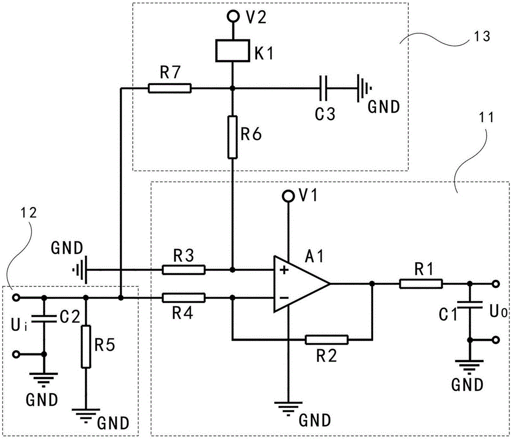
[0003] However, the signal amplifying circuit of the signal processor of the traditional electrical fire monitoring detector can only amplify the load signal of a single nature, that is to say, a signal amplifying circuit can only amplify the inductive load signal, or Either the inductive load signal can only be amplified, so it is necessary to set up two different signal amplification circuits in the signal processor, and the input terminals of the two signal amplification circuits must be connected to the corresponding inductive load signal output terminals, and cannot be connected incorrectly. Or multi-connection, must be connected to a fixed corresponding channel, and must be distinguished, resulting in great limitations in installation, production and use, poor flexibility, once used incorrectly, it may cause circuit damage and affect the accuracy of monitoring and timeliness; From the perspective of cost, the signal processor of traditional electrical fire monitoring detectors cannot maximize the number of inductive loads and resistive loads due to the incompatibility of the signal amplification circuit, which not only increases the purchase cost , and increase the later maintenance cost

Method used


Image

  • The co-signal processor of inductive load and resistive load used for electrical fire supervision

Examples


Embodiment Construction

[0012] The present invention will be further described below in conjunction with accompanying drawing:

[0013] Such as figure 1 As shown, the inductive and resistive load shared signal processor used for electrical fire monitoring in the present invention includes a signal amplifier circuit 11, a current signal conversion circuit 12 and a function conversion circuit 13, and the signal amplifier circuit 11 includes an operational amplifier A1, a first A capacitor C1, a first resistor R1, a second resistor R2, a third resistor R3 and a fourth resistor R4, the non-inverting input terminal of the operational amplifier A1 is connected to the first terminal of the third resistor R3, the inverting input terminal of the operational amplifier A1 Respectively connected to the first end of the fourth resistor R4 and the first end of the second resistor R2, the output end of the operational amplifier A1, the second end of the second resistor R2 and the first end of the first resistor R1 ...


PUM


Abstract

This invention discloses a kind of co-signal processor of inductive load and resistive load used for electrical fire supervision,including signal amplifier circuit and current signal transfer circuit and function transfer circuit, of which the input end of current signal transfer circuit serves as the signal input end of signal processor used to transfer the current signal of inductive load to voltage signal, the function transfer circuit is used to control output low voltage or high voltage according to the type of load practically connected, therefore, the normal work of corresponding signal amplification circuit can be realized. This invention adds current signal transfer circuit and function transfer circuit to traditional amplification circuit to realize the purpose that inductive load and resistive load shares one signal amplification circuit without consideration of area division issue,the installation and production and usage are very easy, the flexibility is high, the supervision accuracy and timeliness is increased. This signal process can connect 2 times of the number of inductive load and resistive load which reduces the cost.

Description

technical field [0001] The invention relates to a signal processor used for electrical fire monitoring in the fire protection industry, in particular to a signal processor shared by inductive and resistive loads used for electrical fire monitoring. Background technique [0002] The electrical fire monitoring equipment in the fire protection industry is a necessary equipment for various buildings, and plays an important role in the prevention and control of electrical fires. The most important electronic equipment is the electrical fire monitoring detector, and its signal processor can automatically The inductive load (such as current transformer) and resistive load (such as temperature sensor) connected to the electrical fire monitoring detector perform signal amplification, processing and signal sampling, including the connection with the load output signal and used to amplify the load output signal Signal amplification circuit. [0003] However, the signal amplifying circ...

Claims


Application Information

Patent Timeline
IPC IPC(8): G01R19/00G01K13/00G08B17/06
CPCG08B17/06G01K13/00G01R19/00
Inventor 王勇廖旭江李佳
Owner CHENGDU XINHAOSI ELECTRONICS DETECTING TECH CO LTD
Learn More