High-energy-saving type cloth pressing electric equipment

An electric equipment and energy-saving technology, which is applied in the field of cloth pressing equipment, can solve the problems of many safety hazards, air pollution, and low heat energy utilization, and achieve the effects of small occupied area, less pollution, and small volume

Inactive Publication Date: 2017-02-01
HUZHOU ELECTRIC POWER SUPPLY CO OF STATE GRID ZHEJIANG ELECTRIC POWER CO LTD +1
View PDF8 Cites 0 Cited by
  • Summary
  • Abstract
  • Description
  • Claims
  • Application Information

AI Technical Summary

Problems solved by technology

However, this kind of coal boiler has low thermal energy util

Method used


Image

  • High-energy-saving type cloth pressing electric equipment
  • High-energy-saving type cloth pressing electric equipment
  • High-energy-saving type cloth pressing electric equipment

Examples


Embodiment 1

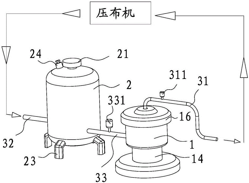
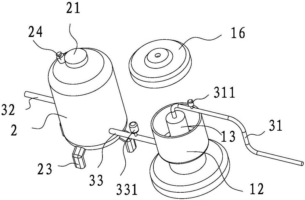
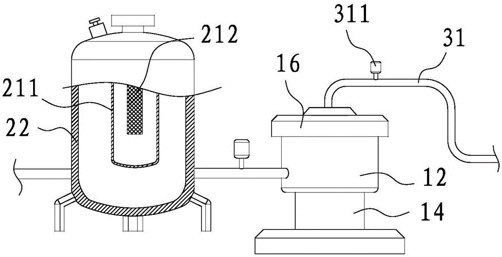
[0034] Such as Figure 1 to Figure 6 As shown, a kind of electrical equipment for pressing cloth is used for pressing cloth onto bamboo products, including a cloth pressing machine, and the cloth pressing machine is connected with heating equipment for heating the cloth pressing machine. The heat supply equipment is an electric boiler. The electric boiler heats the heat-conducting fluid, and then transports the heat-conducting fluid to the cloth press to provide heat for the cloth press. The electric boiler includes a heating furnace 1 and a holding furnace connected to the heating furnace 1 2. The heating furnace 1 is provided with a heating assembly 11 for heating the heat transfer fluid, and the holding furnace 2 is provided with a heat preservation assembly 21 for insulating the heat transfer fluid. The heating furnace 1 transports the heated heat transfer fluid to In the cloth press, the heat transfer fluid flows back to the holding furnace 2 after the cloth press works, ...

Embodiment 2

[0048] Such as Figure 7 As shown, the difference from Embodiment 1 is that the main heating chamber 13 in this embodiment is a hollow cylinder, the convection channel 15 is arranged at the bottom of the side wall of the cylinder, and the heating assembly 11 is also arranged at the main Below the heating chamber 13, the volume of the main heating chamber 13 is larger than that of the first embodiment, and the heat transfer fluid that can be transported at one time is more, which is suitable for a large cloth press.

Embodiment 3

[0050] Such as Figure 8 As shown, the difference with Embodiment 1 is that the structure of the micro-pressure valve 24 is different. The micro-pressure valve 24 in this embodiment includes a shell 246, and the heat preservation cavity 22 is provided with a vent hole 221, and the inner wall of the shell 246 A conical ring wall 247 is provided, and a ball 248 is placed on the conical ring wall 247. When the ball 248 is pressed onto the conical ring wall 247, it just blocks the vent hole from the outside air pressure. When the air pressure is high, the ball 248 is pushed away, and the gas is discharged from the gap between the ball 248 and the conical ring wall 247; The vent hole 221 is isolated from the external air pressure.


PUM


Abstract

The invention discloses high-energy-saving type cloth pressing electric equipment. The high-energy-saving type cloth pressing electric equipment comprises a cloth pressing machine, wherein the cloth pressing machine is used for pressing cloth onto bamboo products and is connected with heat supply equipment for supplying heat for the cloth pressing machine; the heat supply equipment is an electric boiler; the electric boiler comprises a heating furnace and an insulating furnace which communicates with the heating furnace; a heating assembly for heating heat-conduction fluid is arranged in the heating furnace; an insulating assembly which is used for insulating the heat-conduction fluid is arranged in the heat-insulating furnace; the heated heat-conduction fluid is delivered to the cloth pressing machine by the heating furnace; and the heat-conduction fluid flows back to the insulating furnace after the cloth pressing machine works. The high-energy-saving type cloth pressing electric equipment has the advantages of high heating speed, high heat efficiency and small pollution.

Description

[0001] 【Technical field】 [0002] The invention relates to a high energy-saving cloth pressing electrical equipment, in particular to the cloth pressing electrical equipment for pressing cloth onto bamboo products. [0003] 【Background technique】 [0004] Pressing cloth on bamboo products is a necessary part of making bamboo mats. For example, in order to make bamboo mats durable, bamboo mats should be processed by pressing cloth. Cloth pressing is to stick a layer of cloth on the back of the semi-finished mat that has been woven using thermal effect. The cloth pressing process requires adhesives, and the cloth mainly includes chemical fiber cloth, grass cloth, gauze, etc., which can be selected according to needs. According to the working principle of the cloth press machine, the mat and the cloth are glued together more firmly through thermal extrusion, making the mat durable. Traditional cloth pressing equipment mainly uses coal-fired boilers to generate steam during cloth...

Claims


Application Information

Patent Timeline
IPC IPC(8): B32B37/10B32B9/02B32B9/04B32B5/02B32B41/00F24H7/00F24H9/18F24H9/20
CPCF24H7/002F24H9/1818F24H9/2014B32B5/02B32B9/02B32B9/04B32B37/10B32B41/00
Inventor 王伟周敬嵩刘海峰朱林项镭叶彬卢晓勇徐俊
Owner HUZHOU ELECTRIC POWER SUPPLY CO OF STATE GRID ZHEJIANG ELECTRIC POWER CO LTD
Why Eureka
Try Eureka