
Cleaning device for conveying equipment and conveying equipment

A technology of conveying equipment and cleaning device, applied in the direction of cleaning device, conveyor objects, transportation and packaging, etc., can solve the problems of affecting the working environment of the winery, troubled by the cleaning work, loss of cleaning effect, etc., and achieves simple structure and operation. Simple, cost-saving effect

Inactive Publication Date: 2017-02-01
HUNAN BONYA INTELLIGENT EQUIP CO LTD
View PDF13 Cites 9 Cited by
  • Summary
  • Abstract
  • Description
  • Claims
  • Application Information

AI Technical Summary

Problems solved by technology

[0002] In the brewing industry, the use of food-grade stainless steel chain plates to transport grain, wine grains, and grain grains (starch-containing crops) has been recognized by the industry. It has the advantages of excellent conveying effect and little impact on wine quality. The cleaning work has always troubled the winery. It not only affects the overall working environment of the winery, but each shift of workers has a large cleaning workload, and the cleaned grains of the wine can still be used. In order to solve this problem, a steel The brush device, to a certain extent, solved the sticky phenomenon on the non-working surface of the chain plate, but it also brought new problems: after the steel brush device has been in operation for a period of time, the entire steel brush becomes a "starch stick". , the steel brush structure loses its cleaning effect, and it is difficult to clean off the starch on itself

Method used


Image

  • Cleaning device for conveying equipment and conveying equipment
  • Cleaning device for conveying equipment and conveying equipment

Examples


Embodiment Construction

[0020] In order to facilitate the understanding of the present invention, the invention will be described more comprehensively and in detail below in conjunction with the accompanying drawings and preferred embodiments, but the protection scope of the present invention is not limited to the following specific embodiments.

[0021] Unless otherwise defined, all technical terms used hereinafter have the same meanings as commonly understood by those skilled in the art. The terminology used herein is only for the purpose of describing specific embodiments, and is not intended to limit the protection scope of the present invention.

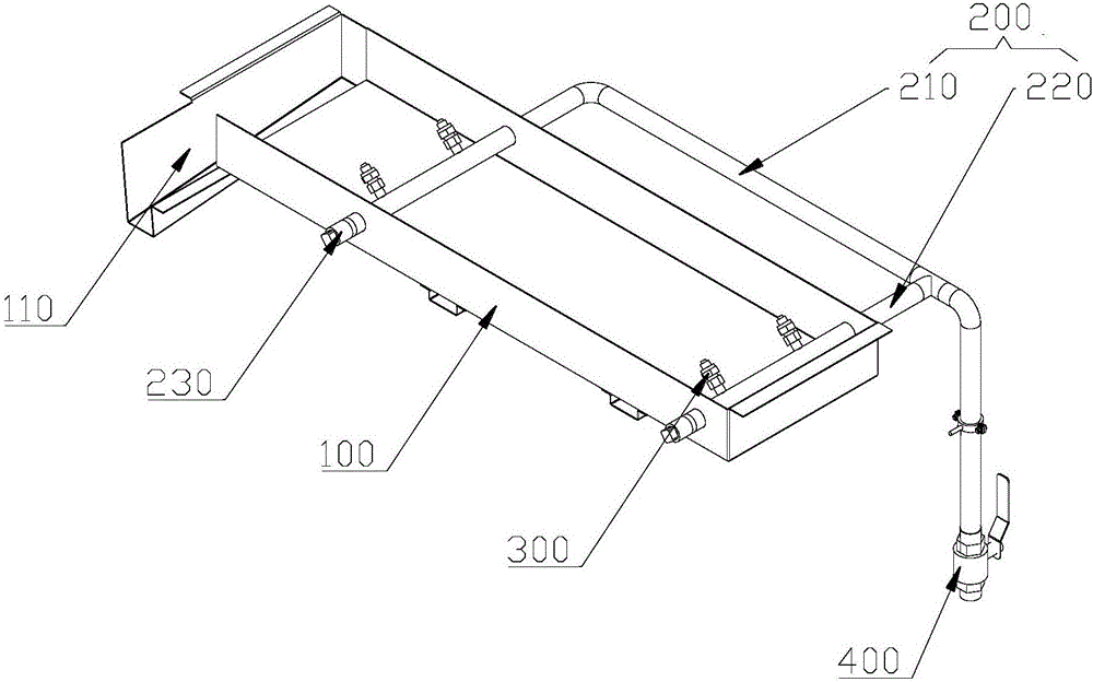
[0022] refer to figure 1 , a cleaning device for conveying equipment according to the present invention includes a receiving tank 100 , a water supply pipe 200 and a spray assembly 300 . Wherein, the receiving tank 100 is arranged under the conveying equipment; the water supply pipe 200 is connected with the spraying assembly 300 for delivering the li...


PUM


Abstract

The invention relates to a cleaning device for conveying equipment and belongs to the field of conveying equipment. The cleaning device comprises a receiving tank, a water supply pipe and spray assemblies. The receiving tank is arranged below the conveying equipment and used for receiving residual materials on the non-working surface of the conveying equipment cleaned by the spray assemblies. The water supply pipe is connected with the spray assemblies and used for conveying liquid materials to the spray assemblies; and the spray assemblies face the conveying equipment. According to the cleaning device for the conveying equipment, the combination of the spray assemblies and mechanisms such as water pipes is adopted to clean the non-working surface of the conveying equipment, the structure is simple, the cleaning effect is good, the operation intensity of a traditional cleaning mode is largely reduced, and the cost is saved; additionally, operation is easy and convenient, as long as a corresponding switch assembly is started and collecting water buckets are placed at the receiving tank and a collecting tank, the fallen residual materials such as grain can be easy to collect and recycle, the cost is reduced, and the cleanliness of an entire factory is improved; and an intelligent control device is adopted to achieve dynamic monitoring on the operating state of the conveying equipment, and the purpose of self-cleaning is achieved.

Description

technical field [0001] The invention is applicable to the field of conveying equipment, and in particular relates to a cleaning device for conveying equipment. Background technique [0002] In the brewing industry, the use of food-grade stainless steel chain plates to transport grain, wine grains, and grain grains (starch-containing crops) has been recognized by the industry. It has the advantages of excellent conveying effect and little impact on wine quality. The cleaning work has always troubled the winery. It not only affects the overall working environment of the winery, but each shift of workers has a large cleaning workload, and the cleaned grains of the wine can still be used. In order to solve this problem, a steel The brush device, to a certain extent, solved the sticky phenomenon on the non-working surface of the chain plate, but it also brought new problems: after the steel brush device has been in operation for a period of time, the entire steel brush becomes a ...

Claims


Application Information

Patent Timeline
Patent Type & Authority Applications(China)
IPC IPC(8): B65G45/22B08B3/02
CPCB08B3/022B65G45/22
Inventor 黄琦蔚潘昊刘川
Owner HUNAN BONYA INTELLIGENT EQUIP CO LTD
Learn More