Variable valve timing mechanism

A valve mechanism and valve technology, applied in mechanical equipment, engine components, machines/engines, etc., can solve problems such as insufficient output, limited engine performance, and insufficient power at high speeds to achieve high fuel utilization. , Improve power performance and fuel economy, and reduce exhaust emissions

Inactive Publication Date: 2017-02-01
ZHEJIANG UNIV
View PDF8 Cites 5 Cited by
  • Summary
  • Abstract
  • Description
  • Claims
  • Application Information

AI Technical Summary

Problems solved by technology

However, this compromise scheme limits the performance of the engine to some extent, including that the output cannot meet the requirem...

Method used


Image

  • Variable valve timing mechanism
  • Variable valve timing mechanism

Examples


Embodiment Construction

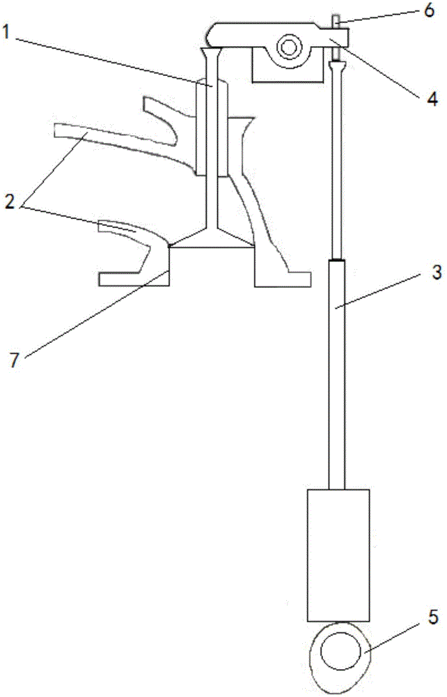
[0025] The invention discloses a variable valve distribution mechanism, such as figure 1 , 2 As shown, it includes a valve 1 and a valve transmission assembly. The valve transmission assembly includes a camshaft, a push rod 3 and a rocker arm 4. The middle part of the rocker arm is hinged to form a lever through the rocker shaft. The rocker shaft is opposite to the cylinder head. 2 fixed, the left end of the rocker arm is against the top of the valve, the right end of the rocker arm is against the top of the push rod, and the lower end of the push rod is against the cam 5 of the camshaft, so The top of the push rod moves up and down, drives the rocking arm to swing around the rocker shaft, and then drives the valve to move up and down. The push rod is an automatically retractable push rod (VPR, Variable Push Rod). When working, the camshaft rotates, and the cam drives the push rod to move up and down. When it swings counterclockwise, the left end of the rocker arm pushes dow...


PUM


Abstract

The invention relates to a variable valve timing mechanism. The variable valve timing mechanism comprises a valve and a valve transmission assembly. The valve transmission assembly comprises a camshaft, a push rod and a rocker arm. The middle portion of the rocker arm is hinged to a cylinder cover, the left end of the rocker arm abuts against the top of the valve, and the right end of the rocker arm abuts against the top of the push rod. The lower end of the push rod abuts against a cam of the cam shaft. The push rod is an automatic telescopic push rod. During operation, the camshaft rotates, the cam drives the push rod to move up and down, the left end of the rocker arm pushes the valve downwards to make the valve move downwards to open an air channel when the push rod pushes the rocker arm upwards to make the rocker arm swing anticlockwise, and the valve moves upwards along with uplifting of the left end of the rocker arm to close the air channel when the push rod falls to drive the rocker arm to swing clockwise; and when the push rod moves up and down, the upward stroke of the upper end of the push rod is changed by changing the expansion and contraction quantity of the push rod, and accordingly the valve opening and closing positions and the stroke are changed. According to the variable valve timing mechanism, valve lift can be adjusted and controlled in a stepless mode, the timing phase is made optimal all the time, and the performance of an engine is remarkably improved.

Description

technical field [0001] The invention relates to an engine valve gas distribution mechanism, in particular to a valve gas distribution mechanism with stepless adjustable valve lift. Background technique [0002] The function of the gas distribution mechanism is to open and close the intake and exhaust valves regularly according to the requirements of the engine firing sequence and the working cycle of each cylinder, so that fresh gas can enter the cylinder in time, and exhaust gas can be discharged from the cylinder in time. Ideally, it is hoped that the amount of gas entering and exiting the cylinder just meets the needs of the real-time working conditions of the engine (including load, operating speed, etc.), so that the engine can perform at its best. [0003] However, the reality is that the traditional valve train consists of camshafts, tappets, pushrods, rocker arms, valves and other parts. The opening of the valves is determined by the lift of the cam on the camshaft, ...

Claims


Application Information

Patent Timeline
IPC IPC(8): F01L1/14F01L1/245F01L13/00
CPCF01L1/14F01L1/245F01L13/0015
Inventor 朱锦浩熊树生刘傲何仲伟胡正浩
Owner ZHEJIANG UNIV
Why Eureka
Try Eureka